Einleitung
Replacing the LCD screen of a Nikon Coolpix 3500.
Werkzeuge
-
-
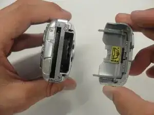
Unlatch the battery cover. Slide the cover out and flip it open.
-
Remove the battery.
-
Gently remove the battery cover.
-
-
-
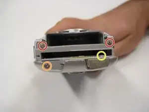
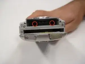
Remove the two 4.5 mm screws that sit next to the battery slot.
-
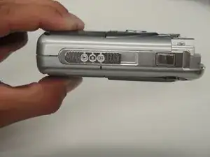
Remove the 3 mm screw that sits below the CF card slot.
-
Remove the 4.5 mm screw that sits above the digital I/O cover.
-
-
-
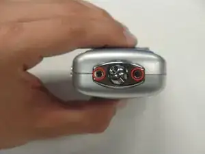
Remove the two 5 mm screws that sit near the camera strap eyelet.
-
Remove the camera strap eyelet.
-
-
-
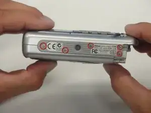
Remove the five 3.5 mm screws that sit at the bottom of the camera.
-
Remove the grey plastic piece, which the five screws held in place, by gently detaching the front cover.
-
-
-
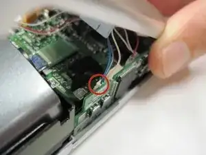
Using a spudger, detach the white-capped wire.
-
Using a spudger, detach the orange-capped wire and set the front cover aside.
-
-
-
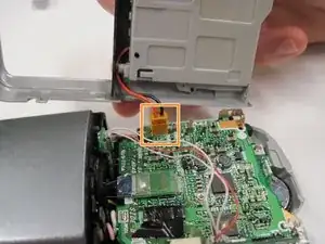
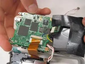
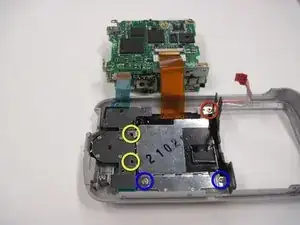
Remove the 3.5 mm screw that sits next to the rotating lens.
-
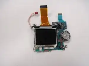
Invert the logic board and lens to uncover the orange and blue ribbon cables. These cables still connect the logic board to the LCD screen.
-
-
-
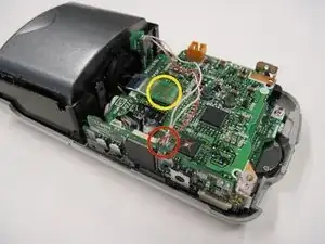
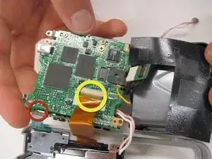
Detach the blue ribbon cable.
-
Detach the orange ribbon cable by using a spudger, and while pushing it out horizontally.
-
Detach the red-capped wire.
-
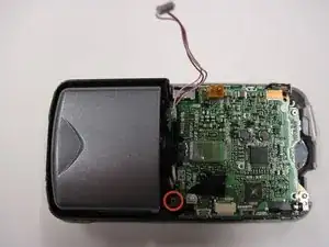
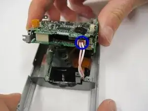
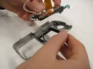
Lift the logic board and lens, which are still connected, out of the back cover.
-
-
-
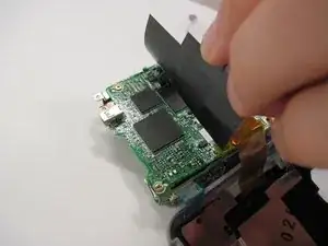
Lift the black covering and remove the orange ribbon cable, which connects the lens to the logic board.
-
To reassemble your device, follow these instructions in reverse order.