Einleitung

The device ports on a digital camera can be prone to damage that may render them nonfunctional. This guide will lead you through the necessary steps to replace damaged device ports.

  1. FSTCFNP5wICffFUe
    FSTCFNP5wICffFUe
    U5PNqESiVh3dEtpG
    Ncj3DDkl6GWjgWNH
    • Remove the battery before beginning.

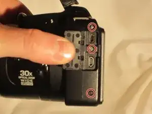
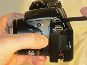
    • Use a Phillips #0 screwdriver to remove the screws on the front casing. There are ten screws, three on the left side, two on the bottom, and one on the right side of the camera.

  2. 6nOR5LUZcdETj1KJ
    6nOR5LUZcdETj1KJ
    IAZsZjNZQBf2MVbE
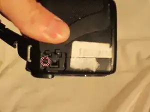
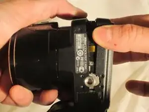
    • Remove the front top Phillips screw with the screwdriver.

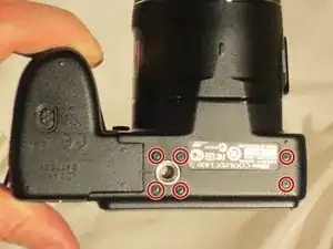
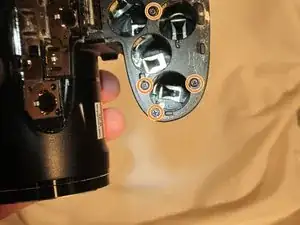
    • Open the empty battery slot on the bottom of the camera, revealing four additional screws.

    • Unscrew the four Phillips screws with the screwdriver.

  3. IkuvIyFUMhZET12q
    IkuvIyFUMhZET12q
    YOIEmINCSKuXGsE5
    djomqIrCiEfaZwBp
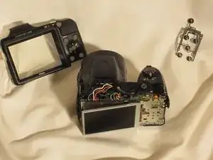
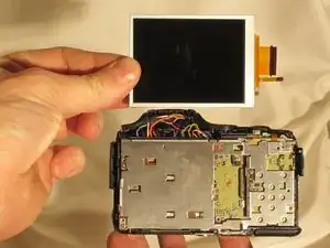
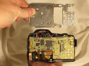
    • Using the spudger, move around the casing, carefully separating the rear housing from the camera assembly.

    • Be sure to only apply pressure to the casing panels and not the sensitive internal electronics.

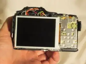
    • Once the rear housing is separated, the settings buttons will be accessible for replacement.

  4. FSO3irhshgsSyT3j
    FSO3irhshgsSyT3j
    Mu1sRkWlA2TOfQlE
    jVOqFxjhaKyBP1Gf
    • Remove the front casing to expose the LCD screen and wires.

    • Do not damage the exposed wires.

  5. KYFI2mMRKxuCWyTs
    KYFI2mMRKxuCWyTs
    XbclNRTbdJT3HVYS
    QlNFDGnpYjvMrTHk
    • Using the tweezers, lift the hinges connecting the two ribbon wires to the camera.

  6. lQR64fLU5wISwnBM
    lQR64fLU5wISwnBM
    MkH21XCfHYHnqqpn
    • Once the flexible ribbon wires are disconnected, remove the LCD screen.

  7. xvDHLckIul1CGXqM
    • Begin by removing these five screws

  8. xtbCXiGZXo1flBKY
    • From there, the panel covering the motherboard can be removed.

  9. KJKEHQ1PQxHkUKXg
    KJKEHQ1PQxHkUKXg
    5y3nBRQoNEy3tylr
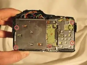
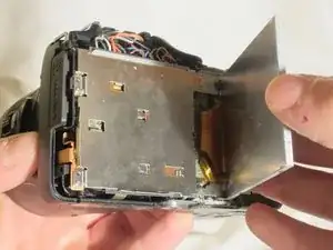
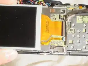
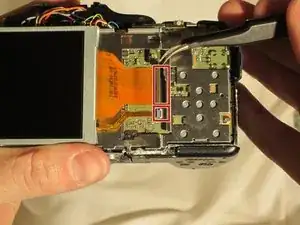
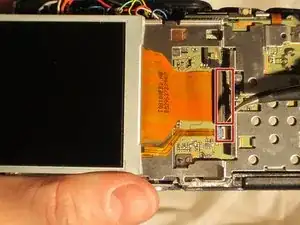
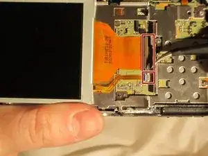
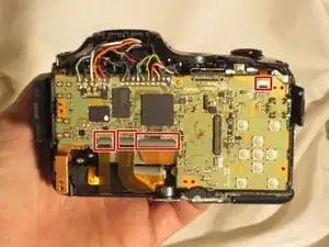
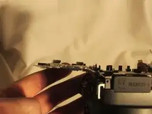
    • Using the pointed end of the spudger, lift the hinges that secure these four flex circuits.

  10. j3rfAuCPeNTilMVc
    j3rfAuCPeNTilMVc
    qDST1cwjUF6dEIDG
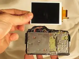
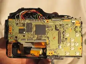
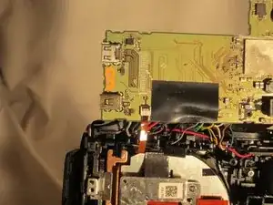
    • Once the flex circuits are removed, the motherboard can be lifted and the device can be accessed for replacement.

    DO NOT “just lift the motherboard"! The motherboard is soldered to a daughterboard for the power button and for the battery compartment. If you do forcibly lift the motherboard you will rip some solder pads off. You need to desolder the motherboard from the daughterboard FIRST before attempting to flip up the motherboard. AFTER desoldering the motherboard there is a singular screw holding in the board in the top left, remove that too!

    Braxton -

Abschluss

To reassemble your device, follow these instructions in reverse order.

Marc

Mitglied seit: 23/03/15

430 Reputation

Ein Kommentar

Could you explain how the power button is changed? Thank you!!

minigalinda -