
Einleitung
If your camera's zoom ability is broken or jammed, you may need to replace the lens portion. Alternatively, if your camera's lens is damaged, you may need to replace the lens.
-
-
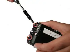
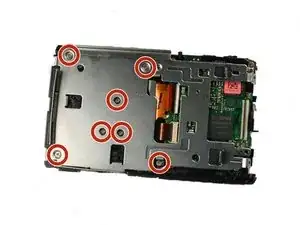
Using a Philips #000 head screwdriver, remove the 8 screws (3.30 mm) visible on the external part of the camera.
-
There are 2 on each side, and 4 on the bottom.
-
-
-
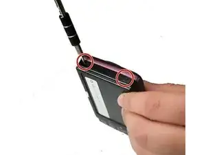
Using the Philips #000 head screwdriver, remove the 1.90 mm internal screw located just above the lanyard mount.
-
-
-
Using the Philips #000 head screwdriver, remove the 3.30 mm screw located on the side of the camera near the lanyard mount.
-
-
-
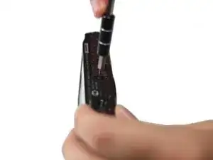
Using the Philips #000 head screwdriver, remove 2 additional 3.30 mm screws holding the lanyard mount in place.
-
-
-
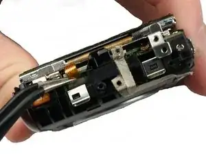
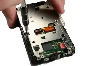
Using the Philips #000 head screwdriver, remove the 3.30 mm screw securing the top shell casing.
-
-
-
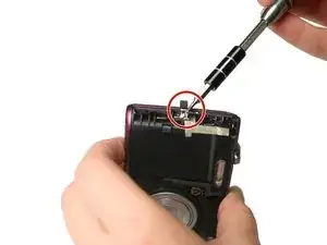
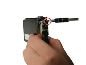
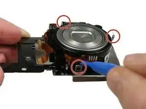
Using the Philips #000 head screwdriver, remove the 3.40 mm screw located on the front of the camera in the upper corner by the LED light.
-
-
-
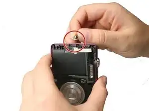
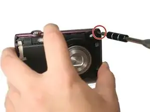
Using the Philips #000 head screwdriver, remove the 3.40 mm screw located near the functional buttons.
-
-
-
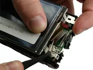
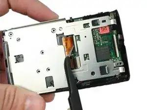
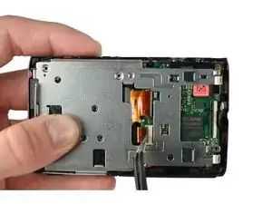
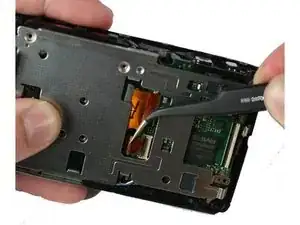
Using precision tweezers, remove the ribbon cable that runs from the functional buttons plate to the under side of the motherboard.
-
-
-
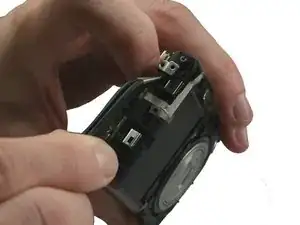
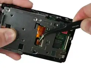
Using precision tweezers, lift up the bottom of the functional buttons plate and remove the metal plate.
-
-
-
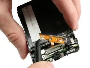
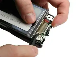
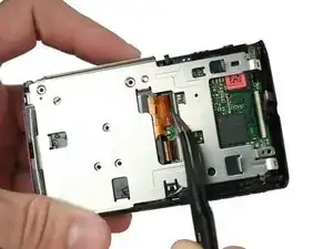
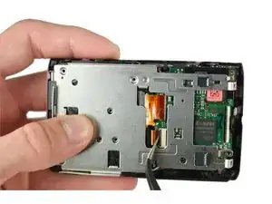
Using precision tweezers, gently remove the ribbon cable running from LCD to the bottom side of the motherboard.
-
-
-
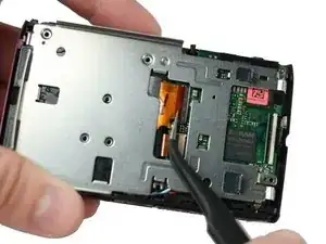
Using precision tweezers, gently lift up on the black strip of the ZIF Connector securing the cable from the LCD to the motherboard.
-
Then, gently remove the wire by pulling the base of the ribbon cable towards the LCD screen.
-
-
-
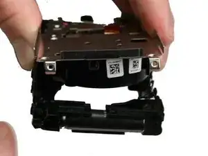
Using a Philips #000 head screwdriver, remove 7 Philips head screws of length 3.4mm from the metal LCD camera mount.
-
-
-
Using precision tweezers, gently lift up on the black strip of the first ZIF Connector securing the cable from the lens to the connector on the motherboard.
-
-
-
Using precision tweezers, grab the base of the first ribbon cable and pull out parallel to the metal mount.
-
-
-
Using precision tweezers, gently lift up on the black strip of the second ZIF Connector securing the cable from the lens to the connector on the motherboard.
-
-
-
Using precision tweezers, grab the base of the second ribbon cable and pull out parallel to the metal mount.
-
-
-
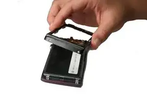
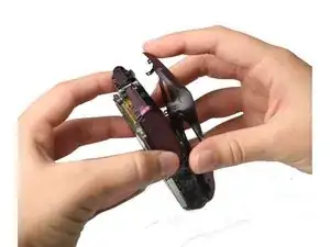
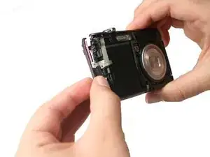
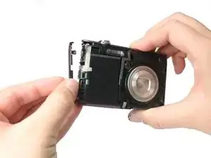
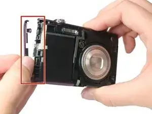
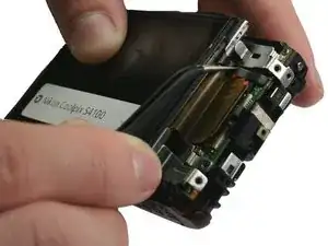
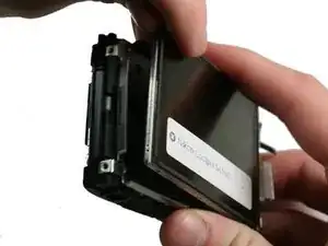
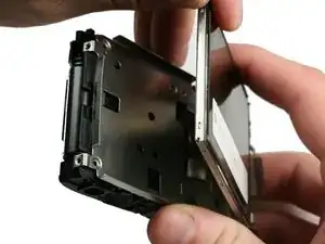
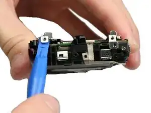
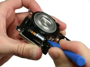
Using a plastic spudger, pry open the 4 clamps on the exterior of the screen mount.
-
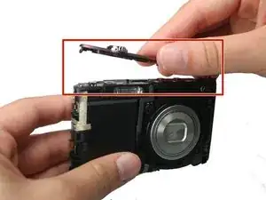
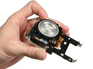
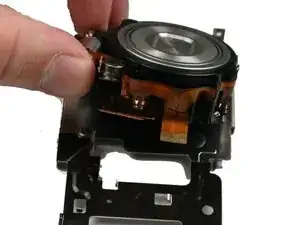
Separate the screen mount and the lens.
-


To reassemble your device, follow these instructions in reverse order.
Ein Kommentar
My screws too stripped. But I thought this would be easy as the discription. Fix your jammed lens!. I haven't fully investigated my ipod touch 5th generation. Which battery needs to be removed to see the flipped side, it looks dirty near the board. Maybe I read wrong… but anyways. That's the best I done…. I just panic. Will try again when I get a screw driver. Or get a magic flash card. That's some folk lore I will try.
Salina -