Einleitung
Werkzeuge
-
-
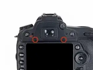
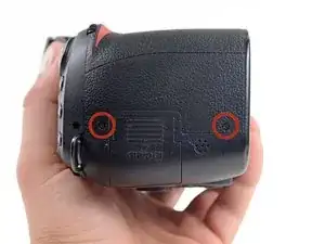
Using a PH000 screwdriver, remove the two 4.8mm Phillips screws from the back of the viewfinder.
-
-
-
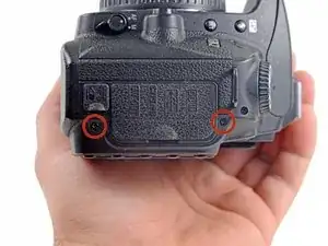
Remove the two 6.4mm Phillips screws on the right side of the camera, near the SD card slot.
-
-
-
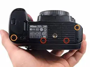
On the bottom of the camera,
-
remove the two 5.3mm Phillips screws
-
and the other two 6.3mm Phillips screws.
-
-
-
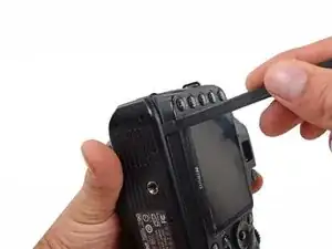
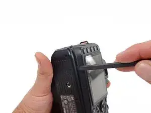
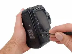
Using a spudger, separate the bottom panel from the rear case just enough to clear the two clips on the rear casing in the next step.
-
-
-
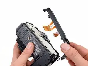
Lift the rear case off of the back of the camera.
-
Be mindful of the two clips, making sure to keep the bottom panel far enough away to clear them.
-
-
-
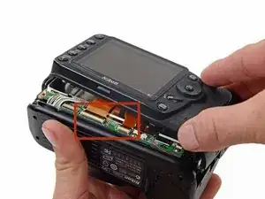
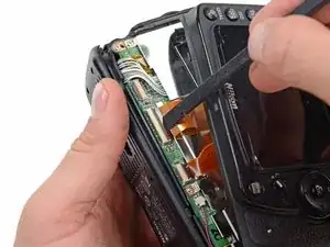
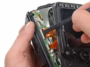
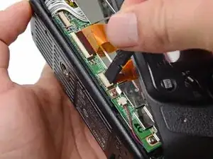
Use a spudger to lift the black tab on the ZIF connector.
-
Disconnect the ribbon cables from their respective ZIF connectors on the logic board.
-
-
-
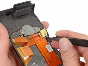
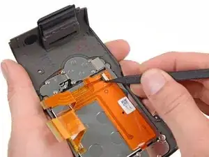
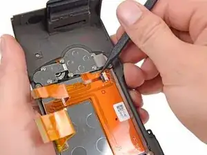
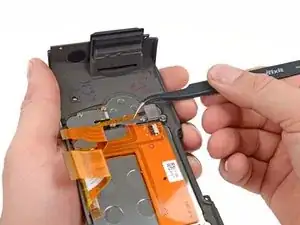
Peel back the yellow tape covering the cable connector on the back of the casing you removed.
-
-
-
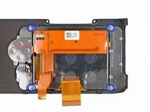
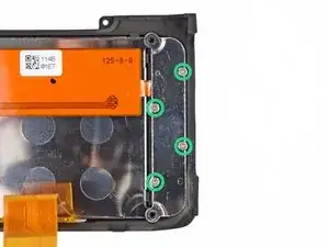
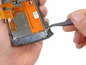
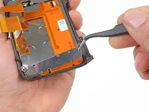
Remove the eight Phillips screws securing the brackets to the rear casing.
-
Four 4.2mm screws securing the large metal bracket.
-
Four 3.4mm screws securing the bracket that covers the ribbon cable.
-
-
-
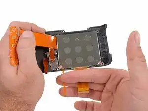
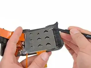
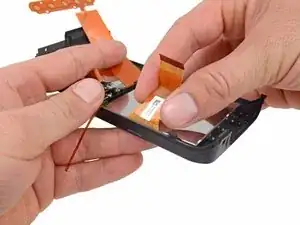
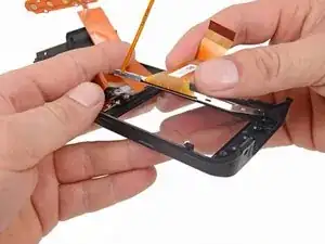
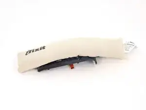
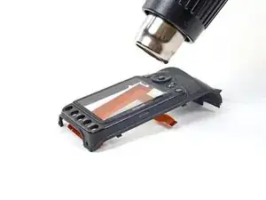
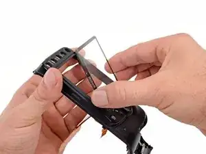
Using either the iOpener or a heat gun, heat the rear LCD glass enough to melt the adhesive holding it on.
-
To reassemble your device, follow these instructions in reverse order.
