Einleitung

A prerequisite for removing the upper LCD.

  1. IbTRcbZ1WV3PGUel
    IbTRcbZ1WV3PGUel
    xCJbCaMh6YXt1hNd
    3It1iWP5mdc1BxA2
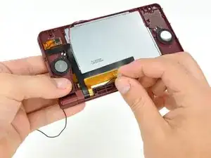
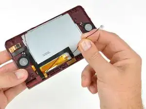
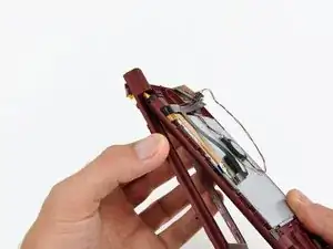
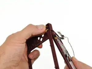
    • Close the DSi XL and turn it over.

    • Using a pair of tweezers, pull the microphone out of its housing in the front bezel.

    • De-route the microphone cable, and pull it through the right hinge.

  2. EvemmZYqudOgDm4Q
    EvemmZYqudOgDm4Q
    MF1NuMTtLbywBNgE
    SG41mDSRr31k5665
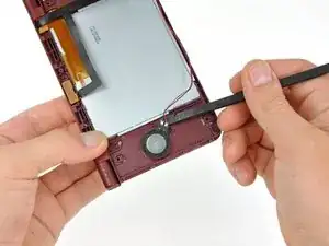
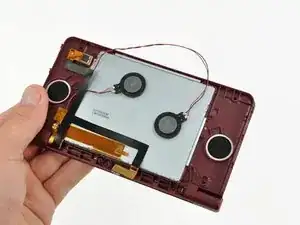
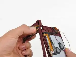
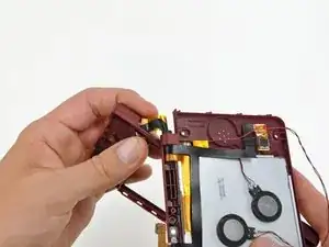
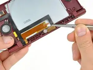
    • Using the flat end of a spudger, pry the left speaker out of its socket on the front bezel.

    • De-route the speaker cable along the top edge of the screen.

    • Work carefully and slowly, holding onto the wire and not the speaker itself. The solder joints may break if pulled on too hard.

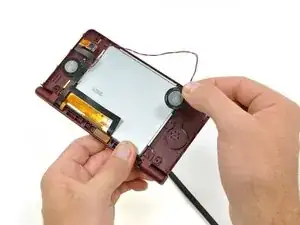
    • In the same manner described above, remove the right speaker from its socket on the front bezel.

    • Place both speakers on the back of the upper LCD.

  3. OmIggiQgdSPOBhHH
    OmIggiQgdSPOBhHH
    q3LhGgPCFFb2WBcU
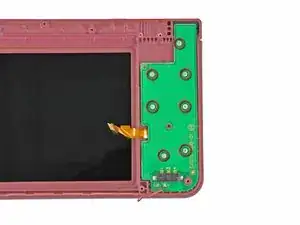
    • Ensuring that the upper LCD does not fall out of the front bezel, turn the DSi XL over.

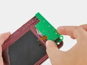
    • Remove the seven 2.5 mm silver screws securing the power board to the upper case.

    • Lift the power board up off the upper case.

  4. vfuGswPSCOGfWwlZ
    vfuGswPSCOGfWwlZ
    ZblaPNMEdLLEU6nR
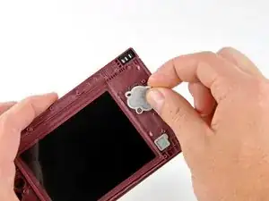
    • Peel the rubber button pads off the backside of the D-pad and power button.

  5. qXcqLvQiTATSp3Sa
    qXcqLvQiTATSp3Sa
    JlHJhPIHX4mM41qQ
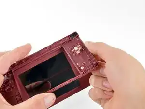
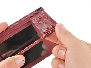
    • Open the case slightly.

    • Push the D-pad up through its housing in the upper case. Remove the D-pad.

    • In the same way, remove the power button from the upper case.

  6. nMvNiGWuljLi2PNY
    nMvNiGWuljLi2PNY
    YYhDJXBuUqCrbm5v
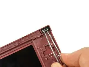
    • Using a pair of tweezers, remove the LED diffuser bracket and the LED diffuser from the upper case of the DSi XL.

  7. k3JsNdZrditFdOUK
    k3JsNdZrditFdOUK
    bR1lgXY1U4S6OqQp
    N4mumRhQI2lYs1yg
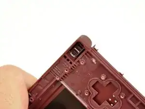
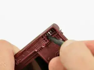
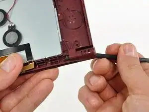
    • In the following steps, you will be using a spudger to remove the hinge pin from the left side of the DSi XL.

    • Place the tip of a spudger in the LED diffuser compartment, on the face of the clutch hinge.

    • Push the clutch hinge to the left.

    • Some force will be required. You will hear an audible "pop" when the clutch has cleared the lower case. It will move about 0.25".

  8. DNBgAIDFbf1hHENE
    DNBgAIDFbf1hHENE
    BRDXIfVxvhFZvBQD
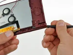
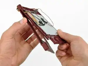
    • Lift the left side of the front bezel away from the upper case.

    • Do not lift too far, or else the hinge pin will break. Only lift enough to clear the LED compartment, about 1".

    • Pull the front bezel to the left, separating the front bezel from the upper case.

    • Do not attempt to fully separate the two halves yet. There are still ribbon cables running through the upper case.

  9. HSVKBO4WVumXWTPP
    HSVKBO4WVumXWTPP
    TIcwqusanpsA4wA3
    5hHNhJjTcBjB6jvA
    • Grasp the camera and upper LCD ribbon cables between your thumb and forefinger, pulling them out of the upper case slightly, slide them down through the slit in the upper case.

    • Rotate the front bezel assembly clockwise so that the ends of the camera and LCD cables slide sideways through the slit in the front bezel.

  10. QKRNlQ6RnHxKYvKG
    QKRNlQ6RnHxKYvKG
    1NTCDSIBiLASFqYK
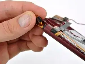
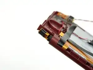
    • In order to remove the upper LCD and the cameras from the front bezel, it is helpful to coil the ribbon cables together.

    • Carefully coil the two ribbon cables together, so that the connectors are on the inside of the spool.

    • Wrap the ribbon cables tightly, but not too tight, as bending the connectors will render them inoperable.

  11. c6OXLrFYOgR1bj4K
    c6OXLrFYOgR1bj4K
    EVsUpWUOOnQ42UEL
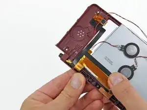
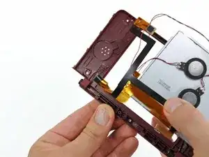
    • Holding the upper LCD and the cameras together, pull the cables through the hinge in the front bezel.

    • Pull slowly, making sure that the cables do not catch on the hinge pin and tear.

    • Uncoil the ribbon cables.

Abschluss

To reassemble your device, follow these instructions in reverse order.
Brett Hartt

Mitglied seit: 13/04/10

125814 Reputation

0 Kommentare