Einleitung

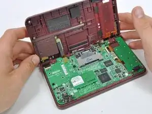
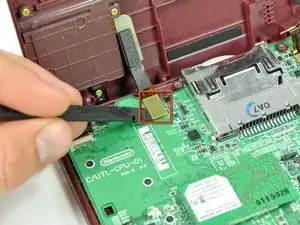
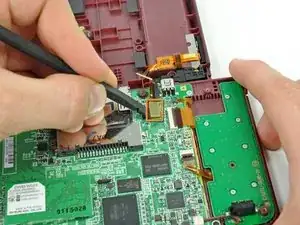
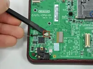
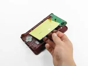
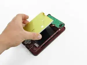
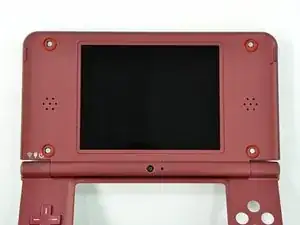
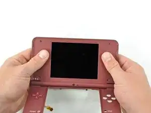
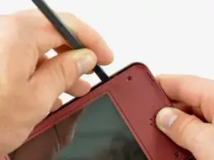
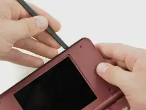
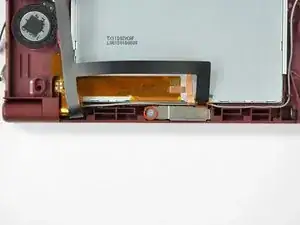
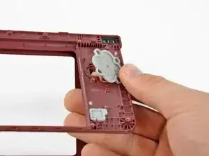
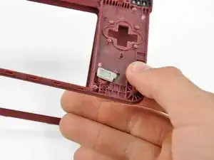
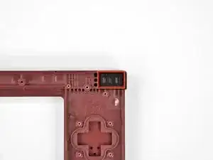
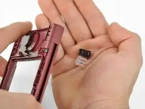
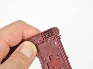
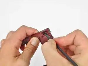
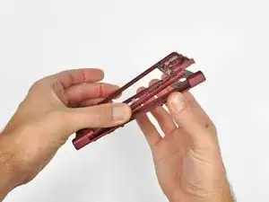
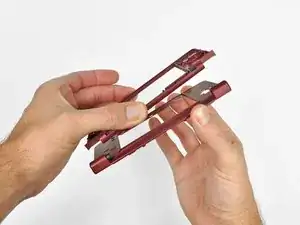
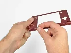
Customize the color of your DSi XL by replacing the upper case.

  1. LIHVnXkBLxLAmFX2
    LIHVnXkBLxLAmFX2
    McyatAIFRiH6Rv4V
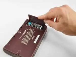
    • Remove the two Phillips screws securing the battery cover to the back of the handheld console.

    • Lift the battery cover off the back of the DSi XL.

    rust/white powder built up on a screw and can’t unscrew it

    Eco -

  2. hBMGuXT2UL1NcEKT
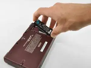
    • Lift the battery from the DSi XL.

  3. DRCcParl5UWTDqOO
    DRCcParl5UWTDqOO
    qXCWLlKGCyOoljVu
    oQRGOhTofiyOef4m
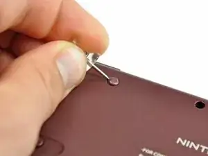
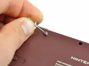
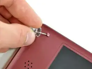
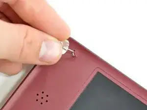
    • Remove the four rubber screw covers on the lower case by prying them up with a push pin.

  4. YcQNLo2uDR3P3KJC
    • Remove the following seven Phillips screws that secure the lower case to the rest of the DSi XL:

    • Four silver 5.3 mm screws

    • Two black 5.3 mm screws

    • One black 2.5 mm screw

  5. BIoYTWlcpQx4cZga
    BIoYTWlcpQx4cZga
    I3ZXKSQk1qDftZHn
    b2CwNLS1EvGSWnR1
    • Turn the DSi XL over, and open the display.

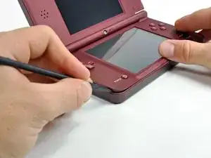
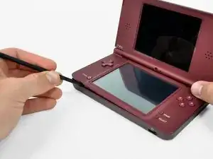
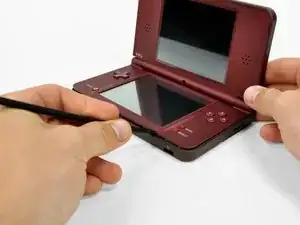
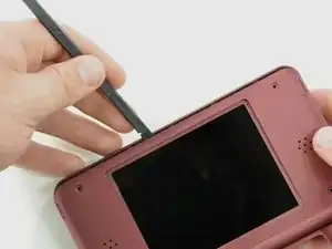
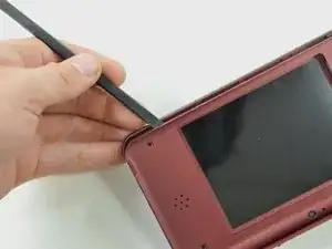
    • Insert a spudger between the upper and lower case at the bottom left corner of the DSi.

    • Slide the spudger along the bottom edge of the upper case to release the latches securing the upper case to the lower case.

  6. nvmvFhfB3IbyUrOD
    nvmvFhfB3IbyUrOD
    2wFkRA6UCXfYgxSC
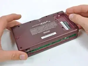
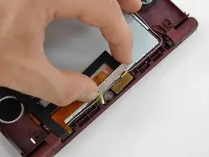
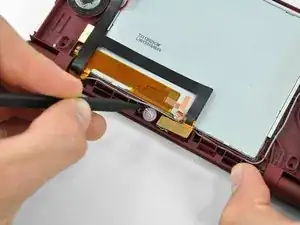
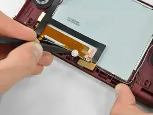
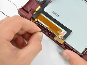
    • Close the display and turn the DSi XL over.

    • Lift the lower case from the front edge.

    • Rotate the lower case away from the DSi.

    • The lower case cannot be completely removed yet, since it is still connected to the motherboard.

  7. naXc3O2Ktm5rO2Tl
    naXc3O2Ktm5rO2Tl
    LOmEVuXMuOgKawjX
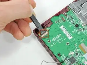
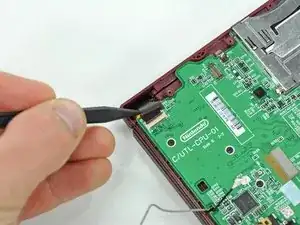
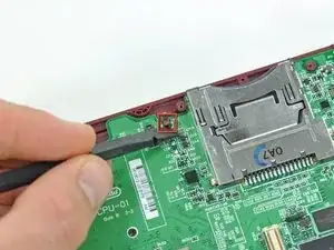
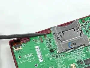
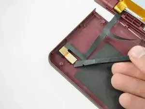
    • Using a spudger, pry the SD card/right shoulder button connector off its socket.

    • Pry the volume button/left shoulder button connector off its socket on the motherboard with a spudger.

  8. DJ3aECMoHqWrwWgx
    • Use a spudger to pry the microphone cable off the motherboard.

    • Pry from underneath the cable.

    Note that the WiFi board has already been removed here! Including this extra step would be convenient here '-)

    Sjoerd Hulshof -

  9. GIjmrSM1o4Clk3WZ
    GIjmrSM1o4Clk3WZ
    dVBKk4rPaolikZho
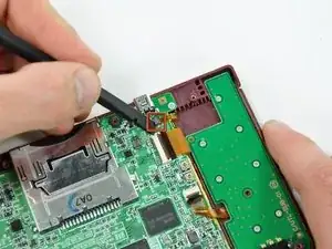
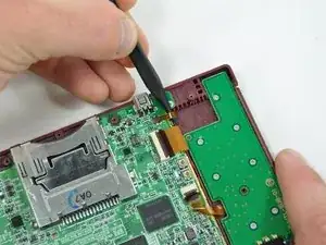
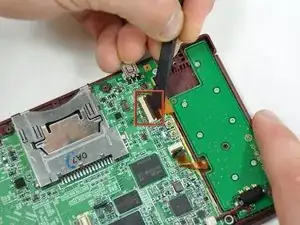
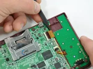
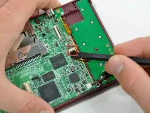
    • Using the flat end of a spudger, flip up the retaining flap on the camera ribbon ZIF connector.

    • Use the pointed end of a spudger to pull the camera ribbon from the ZIF connector.

  10. jULSjpBoaQdNtVE4
    jULSjpBoaQdNtVE4
    KfuXRIrOR2HCDGi4
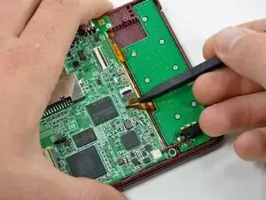
    • Using the flat end of a spudger, flip up the retaining flap on the touchscreen cable ZIF connector.

    • With the pointed end of the spudger, pull the touchscreen cable from its connector on the motherboard.

  11. Itb5IDLLhYO625ut
    Itb5IDLLhYO625ut
    rcPvgusrkhpK4Roc
    • Using the flat end of a spudger, flip up the retaining flap on the backlight cable ZIF connector.

    • With the pointed end of the spudger, pull the backlight cable from its connector on the motherboard.

  12. ZfjtZBdkTOorxXsu
    ZfjtZBdkTOorxXsu
    ZMWuTQfrnRTEjkYU
    • Using the flat end of a spudger, flip up the retaining flap on the lower display data cable ZIF connector.

    • With the pointed end of the spudger, pull the lower display data cable from its connector on the motherboard.

    -This is where you can replace the charger port. i may change this comment later from May 21-June 5

    Artemy Matveev -

  13. IVS53wyRXhabZeMG
    IVS53wyRXhabZeMG
    u5DepNx2ReGZxKMq
    • Using the flat end of a spudger, flip up the retaining flap on the ZIF connector for the D-Pad/power button cable.

    • With the pointed end of the spudger, pull the D-Pad/power button cable from its connector on the motherboard.

  14. S6MyOrlhJq5J1jn3
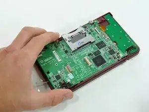
    • Using the flat end of the spudger, pry the battery cable up off its socket on the motherboard.

    The battery connectors (socket) on the mother board are extremely fragile, so care should be taken to avoid breaking them.

    Other than this, the instructions given are precise and straighforward. I do agree with the other comments about step 20.

    Paulette Williams -

  15. KRmwdgntnPUfXxPT
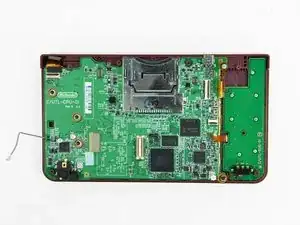
    • Remove the screws securing the motherboard to the upper case:

    • A single 2.5 mm silver Phillips screw

    • Four 3.7 mm black Phillips screws

    the battery connector was (for me) extremely hard to remove. I broke the socket completely off the board hand had to hard solder it directly back.

    Rohan Grant-Dawes -

    On Step 17, I only had the 3 black Philips screws on the left to remove.

    bfmackin -

  16. dT1iKAsnLJji6Jks
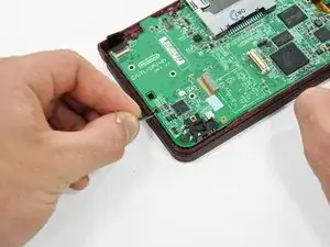
    • Deroute the microphone and antenna cables through the slot in the motherboard.

  17. ou3yBIQeB1bXYUbt
    ou3yBIQeB1bXYUbt
    UWKbdTyfVeybbXcy
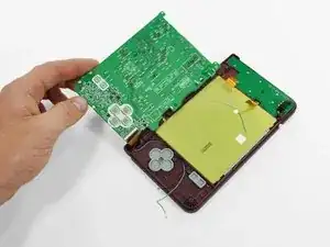
    • Rotate the motherboard off the lower case.

    • The motherboard cannot be completely removed yet. It is still attached by the upper LCD's display data ribbon cable.

  18. x4a1E31XYdsi5bGo
    x4a1E31XYdsi5bGo
    2qQXVACkIpQMHyXE
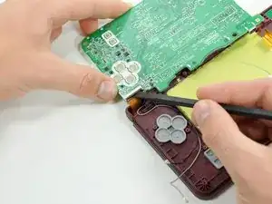
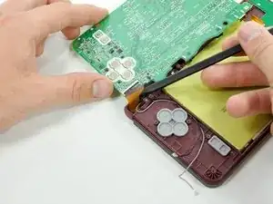
    • Using the flat end of a spudger, flip up the retaining flap on the upper display data cable ZIF connector.

    • With the pointed end of the spudger, pull the upper display data cable from its connector on the underside of the motherboard.

    • The motherboard is now free from the upper case.

    This step is unnecessary. The ribbon is a total pain in the butt to get back in, and if you dont get it PERFECT, the DS will not even fire back up. Unless it is absolutely necessary to remove it... DON'T !!! ( Personal experience, Everything else was SPOT ON) THANK YOU FOR THE HELP, saved me a lot of $$$

    Jerod Cook -

    Completed, worked perfectly! I agree with the comment about step 20, completely unnecessary.

    ian -

    Fantastic! Fixed my daughter's irreplaceable DSi XL - you should see her smiles!! Not sure about step 20 I did this before reading the comments (guess there's a message there). Thanks so much whoever wrote this - you're a legend and you've made a child very happy (and a dad too thereby).

    lb9 -

    I put mine back together for my daughter with the new bottom screen, but it won't power on. It tries but won't I'm assuming that this ribbon is the cause.

    bigdrum1998 -

    The instructions are perfect though! Great thing to have these instructions it's a tremendous help! :-)

    bigdrum1998 -

    YHWH is the god of all knowledge. Put a piece of transparent tape on the ribbon cable to give more leverage to pull the cable up to slide it into the slot. Also turn the motherboard slightly so that you can get it closer to the cable.

    Deanna Cortez -

    I didn't get mine completely reinserted at first. The symptom I experienced when powering it back on is the power light comes on briefly and the bottom screen light flashes, then they both shut off. No flash from the upper display. Had to try reinserting 3 times before I had it in completely. I agree, DON'T REMOVE if you don't have to.

    bfmackin -

    DONT follow this step, i missed these comments and removed my cable, it took me almost an hour (I know, way too long, I just couldn't get the cable far enough in to the slot) before the top screen finally worked. Was afraid I destroyed the cable, but it survived luckily enough.

    SaakS -

  19. 1lUN2j4wp4Yq1UjB
    1lUN2j4wp4Yq1UjB
    AOPN1b1MXMUKRi1A
    • With the console still upside-down, open the DSi XL slightly.

    • Push the lower display away from the upper case.

    • Remove the lower display from the DSi XL.

  20. WCWCsX3Ugt3CR3bK
    WCWCsX3Ugt3CR3bK
    APoZXhmByvIsNwyU
    GKMXRiv21oZJMNEq
    • Turn the DSi XL over and open the display.

    • When re-assembling the device, be sure to re-install the ABXY and Start/Select buttons, as they are likely to fall out once the handheld console is turned over.

    • Use a pushpin to remove the four plastic screw covers on the front bezel.

  21. ZDbiZU1x4SWCrwLE
    • Remove the four 3.5 mm silver Phillips screws securing the rear bezel to the front bezel.

  22. bG5wNTevMBxWtyr1
    bG5wNTevMBxWtyr1
    34MQvTrliHvTjywM
    • Using two hands, gently slide the rear bezel upwards.

    • The rear bezel will move only about 2 mm.

  23. IZagquLTLDPWfYhK
    IZagquLTLDPWfYhK
    tPCjk2NeSdLiKjVL
    • Insert a spudger into the gap between the front and rear bezel.

    • Rotate the spudger away from the DSi XL, prying the two bezels apart.

  24. Jia1HTKPBUCXWrkH
    Jia1HTKPBUCXWrkH
    N6krZ64usYrtD6bF
    • In the same manner as described above, continue prying along the top edge of the front and rear bezels.

  25. 5IuDs6IBxoVIwu2j
    • Separate the rear bezel from the front bezel.

    • Do not attempt to completely remove the rear bezel yet. It is still attached to the front bezel by the rear-facing camera.

  26. BHkYPeN1boYsOMfX
    • Using the flat end of a spudger, pry the rear camera off the rear bezel.

    • Remove the rear bezel.

  27. chPEHjmEas5ZJw3A
    chPEHjmEas5ZJw3A
    XnQ1CLsRpgymDBE1
    • Remove the Phillips screw holding the metal securing bracket in place.

    • Lift the metal bracket off the camera.

  28. GEXIgRCKNRwYlSUO
    GEXIgRCKNRwYlSUO
    ylGd2rprGd5JGqYj
    • Use the tip of a spudger to lift the microphone from its seat on the front display bezel.

  29. XhSUGSOM1UwvyfEy
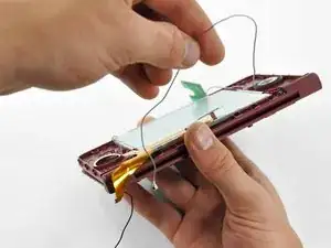
    • De-route the microphone cable.

  30. HHA3JXQXbYNK6PaF
    HHA3JXQXbYNK6PaF
    wWRjGUnG2SqlHQfv
    HeUBW1CHXlVhuJuP
    • Pull the microphone cable through the right hinge connecting the front bezel and upper case.

    • Use the pointed end of a spudger to guide the connector at the end of the microphone cable through the hinge.

    • To replace the microphone, use a pair of tweezers to guide the connector through the hinge.

  31. VLYIYWLeuPBUdZWU
    VLYIYWLeuPBUdZWU
    SJps3UZf22oDgZae
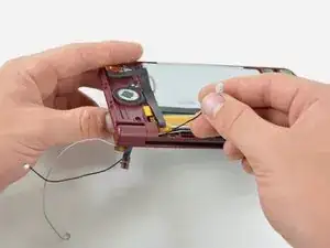
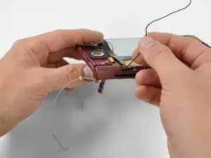
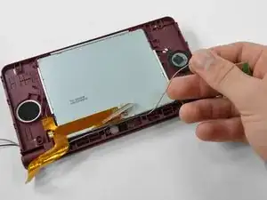
    • Lift the Wi-Fi antenna off the front display bezel.

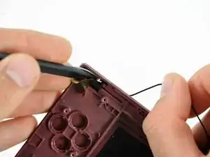
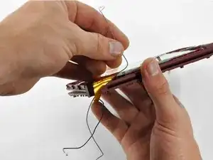
    • De-route the Wi-Fi antenna cable from its grooves at the bottom of the front display bezel.

  32. PuuUGWXEtVbb2Hin
    PuuUGWXEtVbb2Hin
    PKbyV1KIsjIj5dOa
    • Pull the Wi-Fi antenna cable through the right hinge connecting the front bezel and upper case.

  33. hnlqCeRps2gcqNiy
    hnlqCeRps2gcqNiy
    ELRkNyAvNpGorkJu
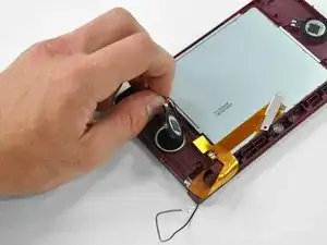
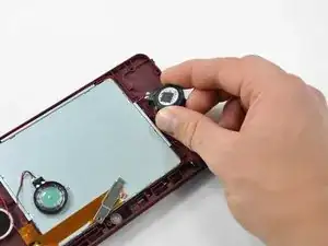
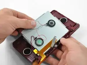
    • Lift both of the speakers from their seats on the front display bezel.

  34. NSTRL4fgYgFlrrPq
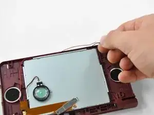
    • De-route the speaker wires that run above the upper display screen.

  35. aStyMOGPowvuyTmW
    aStyMOGPowvuyTmW
    WwAMKpqwREwFkRTa
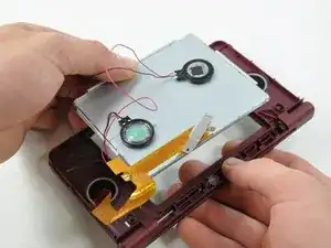
    • Remove the upper display assembly.

  36. lHMMyNaIUweoONPs
    lHMMyNaIUweoONPs
    ak4TwZxPVhpZoNtN
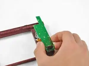
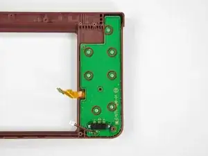
    • Remove the seven 2.5 mm silver screws securing the power board to the upper case.

    • Lift the power board off the upper case.

  37. 5sLV6HcLgArAiPG6
    5sLV6HcLgArAiPG6
    NKZaMjNvPhkh2cft
    • Open the case slightly.

    • Push the directional pad up through the upper case and remove it from the upper case.

    • Push the power button up through the upper case, and remove it from the upper case.

  38. 6EHLa1xor2u6YCGP
    6EHLa1xor2u6YCGP
    XAHLoSaJYKZQoAjq
    • Remove the LED diffuser and black retaining bracket by turning the upper case upside-down and letting both pieces fall into your hand.

  39. a5CtLJvi2NFUlYXv
    a5CtLJvi2NFUlYXv
    WLNXD42AYwkKGQfg
    • The front bezel is held in place by the clutch hinge on the left side of the DSi Xl=L.

    • Using the tip of the spudger, push the clutch hinge to the left.

    • You will hear a "click" when the clutch has been completely displaced. Some force will be required.

  40. diKAl4v1deYeSQCM
    diKAl4v1deYeSQCM
    A31TRQPPyo21Xuxl
    • Lift the front bezel off of the upper case, tilting the left side of the front bezel away from the upper case first.

  41. 5w2raQPIrgR2xuOo
    • Remove the hollow hinge pin from the right side of the DSi XL.

    • The upper case remains.

Abschluss

To reassemble your device, follow these instructions in reverse order.
Brett Hartt

Mitglied seit: 13/04/10

125814 Reputation

0 Kommentare