Einleitung
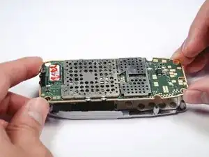
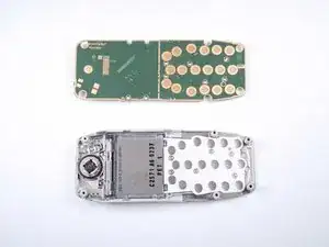
This guide shows how to replace the logic board.
Werkzeuge
-
-
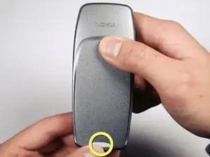
Press down on the back of the phone with your thumb. Then slide the back plate upward toward the top of the phone.
-
Lift the back plate off the phone.
-
-
-
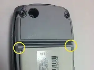
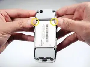
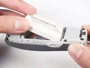
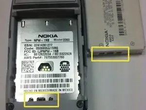
To release the battery, press the two tabs that are located directly above the battery towards the top of the phone at the same time.
-
-
-
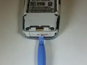
Use a pry tool towards the bottom of the phone to gently detach the face plate from the dark grey phone frame.
-
Hold phone frame down while separating the face plate.
-
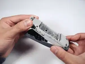
Separate the faceplate and grey phone frame.
-
-
-
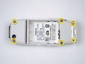
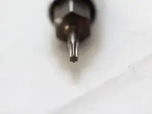
Remove the six screws using a T6 screwdriver. (refer to second picture to help identify T6 screwdriver head).
-
-
-
Place the phone with the screen facing down onto a flat surface.
-
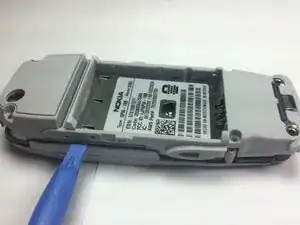
Place the flat edge of the pry tool into the seam on the side, just above the screen. (refer to picture on where to place pry tool).
-
Push the pry tool into the seam.
-
Pry apart the plates until the cover separates from the rest of the phone. Be careful not to apply too much pressure
-
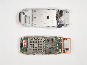
Proceed to pull the front cover away from the rest of the phone. (refer to second picture for results) The marking foreshadows what we will be using in the next step.
-
-
-
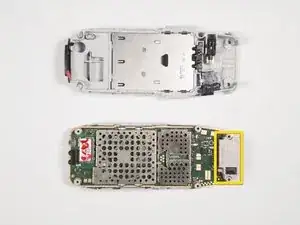
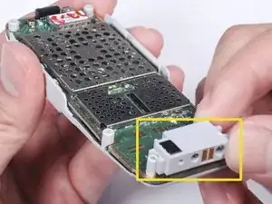
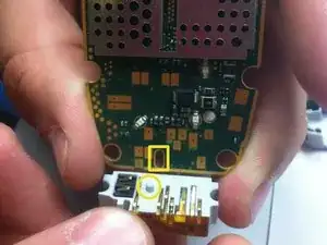
Locate the charger connector. (refer to picture with marker)
-
Carefully lift the charger connector upward to detach.
-
-
-
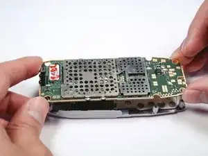
Once the charger connector is pulled out, proceed with removing the logic board.
-
To remove the logic board, grip the four corners of the logic board and lift from the front inner case.
-
To reassemble your device, follow these instructions in reverse order.
