Einleitung
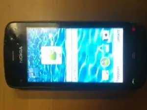
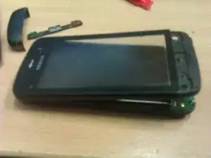
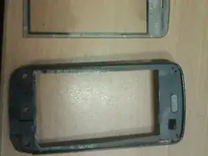
Well repairing phones can sometimes be an easier task or sometimes quite a difficult one. Recently we had a customer request a repair on a Nokia C5-03, naturally I checked ifixit.com, with no luck and without being able to find any other guides, decided to delve in and see what happens overall it isnt too difficult but may require some force in places, so if you arent game to put a bit of presure on it, this guide isnt for you, there may be a better way, but this is how I did, hope it helps someone replace their damaged touch screen.
Werkzeuge
Ersatzteile
-
-
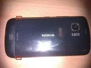
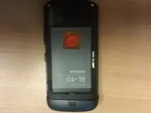
Pry the rear cover off the C5.
-
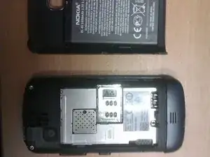
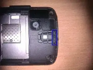
Upon removing the rear cover, the back side is left exposed.
-
-
-
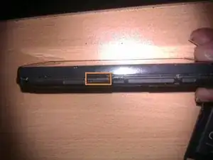
Remove the microSD card (highlighted in orange) from its recess within the inner framework of the C5.
-
-
-
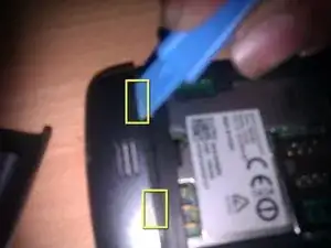
Carefully wedge the flat end of a plastic opening tool between the rear cover and inner framework.
-
Pry upwards to release the clips securing the bottom cover.
-
Repeat with both clips until the bottom cover is released.
-
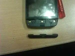
Lift and remove the bottom cover away from the C5.
-
-
-
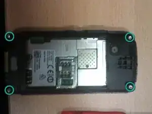
Remove the following screws securing the inner framework and its plastic surround to the rest of the C5:
-
Four T6 Torx screws.
-
-
-
Wedge the flat end of a plastic opening tool between the front panel assembly retaining clip and the outer case (highlighted in blue).
-
Carefully pry the opening tool upwards to release the retaining clip securing the upper portion of the front panel assembly.
-
Run the flat edge of a plastic opening tool around the perimeter of the front panel assembly to release the remaining retaining clips.
-
-
-
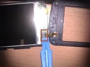
Use the flat end of a plastic opening tool to pry the digitizer cable connector up and out of its socket on the motherboard.
-
-
-
Using a heat gun or hairdryer, heat the top area of the front panel assembly for approximately 20 seconds.
-
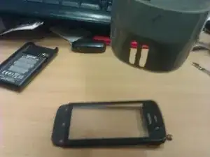
Use your fingernails or a plastic opening tool to separate the glass from the front panel assembly. The glass is held to the front panel assembly by adhesive, it may require some work to free it.
-
To reassemble your device, follow these instructions in reverse order.
