Einleitung

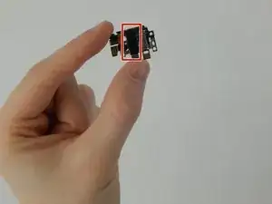
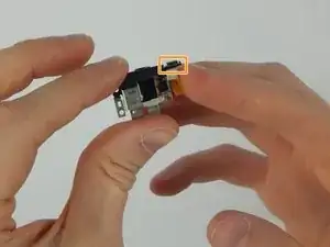
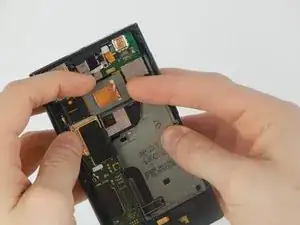
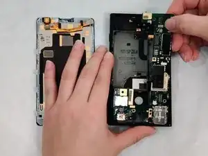
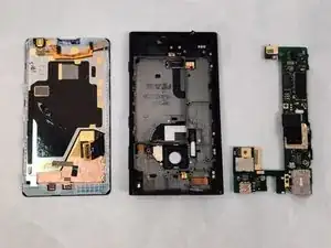
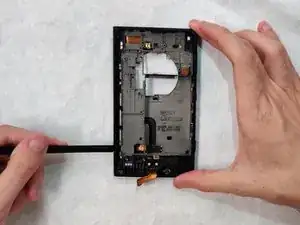
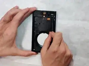
This guide will describe how to remove the charging port of your Nokia Lumia 1020.

This replacement will be useful if you want to replace a damaged charging port. Most commonly, charging ports can be damaged from accumulating debris or water damage. If you are having issues charging your device, you may want to consider replacing the charging port.

  1. RRLgk2QLrKuCeZBU
    RRLgk2QLrKuCeZBU
    lVHTqSC3VodLXW2o
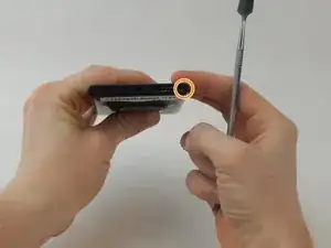
    • Use a SIM door key to remove the SIM card and SIM card tray from the device.

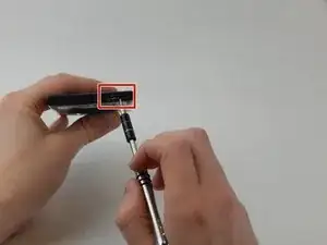
    • Use a T4 screwdriver to loosen the captured torx screw to the right of the SIM card tray (the screw will not come out).

  2. gm4gCONVPnsQRUsN
    gm4gCONVPnsQRUsN
    bTM2bXrgJfxSNsJV
    2qEEahAHCdHfsakr
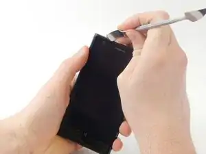
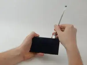
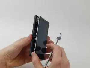
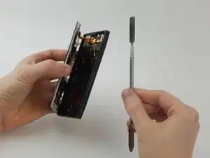
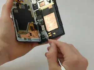
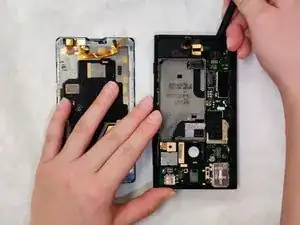
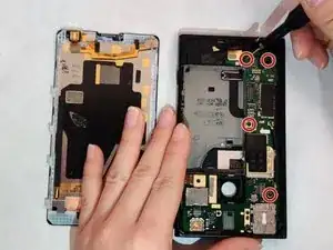
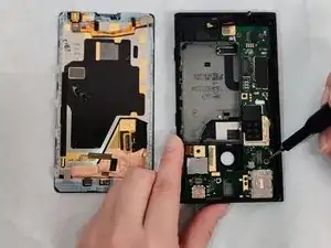
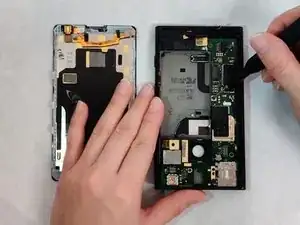
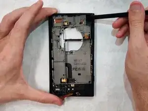
    • Wedge a spudger in between the screen and the back of the device, starting from the top left corner of the phone.

    • Gently pry the screen away from the back of the device using slight upward pressure.

    • Slide the spudger down towards the bottom left corner of the device, continuing to gently pry upwards. The screen will now be slightly separated from the back of the phone.

    oh be really careful. Thisprocess resulted in a damaged screen.

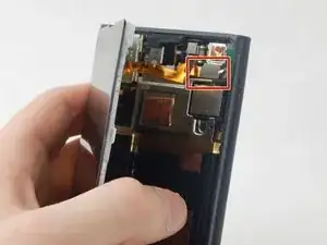
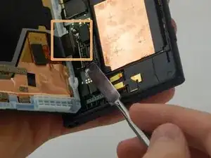
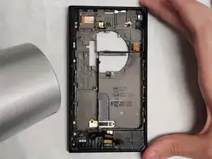
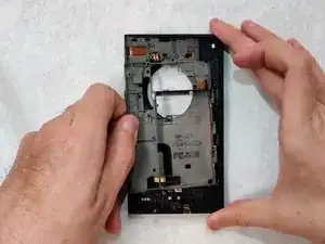
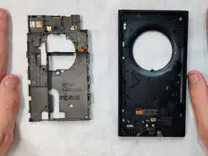
    If you study the third picture above you see that the left hand side is a line of hooks. The right hand side is a line of flat bars that lie under the plastic of the plastic frame.

    So: lever the frame away from the glass on the right hand side first.

    then slide the glass towards you, thereby disengaging the hooks.

    I wish you better luck than I had.

    Julian Baker -

    On reflection I think it would be better to start on the Left hand side first; as per the original instructions as there is less distance for the frame to be bent before the hooks are releases. Sorry for any confusion.

    Julian Baker -

  3. ZDZoxcBrKndNSqqq
    ZDZoxcBrKndNSqqq
    LM1JTSJBKjYoFEwb
    11oTrFumS6ElnGLY
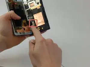
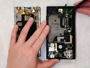
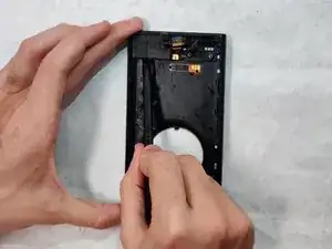
    • Wedge a spudger underneath the silver rectangle in the upper right corner until it pops off the back of the phone.

  4. 2aMjgqtqErgvEcd2
    2aMjgqtqErgvEcd2
    Dxt4l2CWfseDaUpb
    wXLpWyKejXmAyalF
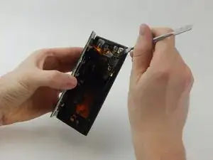
    • Wedge a spudger underneath the silver rectangle in the lower left corner until it pops off the back of the phone.

    • Completely remove the screen from the back of the phone.

  5. HVpfLbwO3NAkhcvD
    HVpfLbwO3NAkhcvD
    WpK631qy26XVcILA
    FqGkXiwiMHfSuHCA
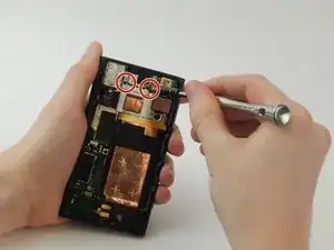
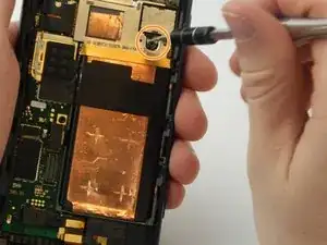
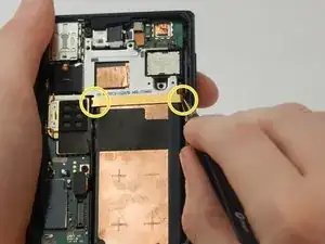
    • Unscrew the two 4 mm torx screws on the top silver strip with a T4 screwdriver.

    • Unscrew the 4.5 mm torx screw above the gold bar with a T6 screwdriver.

    • Grab the edges of the gold strip with gripped tweezers to remove. The gold and silver metal will come off together.

  6. YOBDN6ukJQAepaXC
    YOBDN6ukJQAepaXC
    bbCLicWfIJkEBnWe
    kUjRQjI6KfWTcPlx
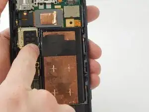
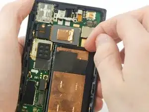
    • Be careful not to puncture the battery. Use a spudger to slice the black tape on the left side of the battery.

    • Remove the battery with your finger.

    • Wedge a spudger underneath the small black rectangle attached to the battery until it pops off.

    The battery is locked into place with two notches on either side of the lower part of the battery (towards you opper side). These fit unter ears on the grey frame.

    so lever the old battery up from the right hand side ensuring the top part lifts first. once the top is proud of the grey plastic move the battery upwards to disengage the notches from the ears.

    Replacing the battery:

    Firstly connect the battery connector There’s a helpful golden line that marks the edge of the battery connector. Then snuggle the new battery under the ears at the bottom first, then push it down and into place.

    Julian Baker -

  7. SdC6BHPQo2N1ATHg
    SdC6BHPQo2N1ATHg
    UJSSYwA4QYha2aoW
    DtUJOEVVZb4XAjZS
    • Use the T4 screwdriver to remove the 4 mm torx screw.

    • Remove the headphone jack by pulling back on the silver plate with your fingernail.

  8. Eb2jmBHqSHZiEolu
    Eb2jmBHqSHZiEolu
    FmdfeFLv3XSUmeUH
    4DdoPMNEGvZkDkyX
    • Remove the headphone jack with spudger.

    • Wedge the spudger underneath the grey rectangle and pry until it pops off. Note this piece is glued and may require more force than previous rectangles.

    • Headphone jack is fully removed and can be replaced.

  9. HEi1mnFRt3pHG4Zx
    HEi1mnFRt3pHG4Zx
    RXmVp2jTajIfJ1C3
    6aHStbsZSGsapVJr
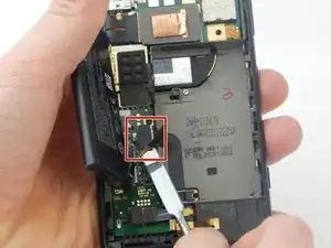
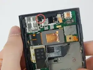
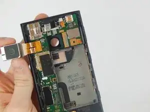
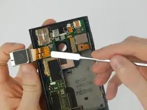
    • Use your fingernail to grip the rear-facing camera on the upper middle part of the back of the phone. Pry until it pops off to the left.

    • Remove the camera by wedging a spudger underneath the attached gold foil.

  10. vGhjnggNiiYKEarK
    vGhjnggNiiYKEarK
    FJWGBkqllSkFvkMY
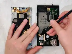
    • Disconnect the two gold connectors from the motherboard using a spudger.

    • Be gentle with the connectors to make sure they are not damaged.

  11. NcrkZMhXWZVShtVN
    NcrkZMhXWZVShtVN
    JCXjjQlGFRwM4QhA
    sFj1rCnYNvO5pQC1
    • Using a T4 screwdriver, remove four 4.60 mm screws to disconnect the motherboard from the rest of the device.

    • Be sure not to lose the screws.

  12. ZbI5Zpryr2G1MDQJ
    ZbI5Zpryr2G1MDQJ
    DKvPugUASEIxU3Hw
    Yj6CFeEYrpZor5mC
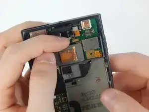
    • Use the spudger to remove motherboard first from the top right corner, then bottom right corner, then the bottom left corner.

    • After loosening the motherboard, begin to remove the component by starting at the top right corner first, then pull motherboard out.

  13. uwWPpMtQpPZCJIZO
    • Using a T4 screwdriver, unscrew four 4.60 mm screws to disconnect the rear camera casing from the rest of the device.

  14. mawdH5XAY5fXImIi
    • Use a hairdryer to heat up the adhesive of the plastic base. This may take around 5 minutes.

    • This may take more than 5 minutes. Also, the iOpener by itself may not provide enough heat to truly melt the adhesive.

  15. 1Twh2giBQSM1SIXc
    1Twh2giBQSM1SIXc
    qPurbMMI6YsXyijP
    NG6pEVJF5oDcRU6b
    • Insert the spudger on the edges of the base and lift up.

  16. bSDDWbbwIj5C6Hm4
    bSDDWbbwIj5C6Hm4
    BehhIgAh1TBj2jcI
    • Now that the base is loose, lift it with your fingers and separate it from the case.

  17. X52xYjIOSB5EZ3aS
    X52xYjIOSB5EZ3aS
    XJKBh52HsViJbNUb
    iIUg1umXhDZJBigZ
    • After removing the base, slide the spudger in underneath the speaker, and slide the spudger across.

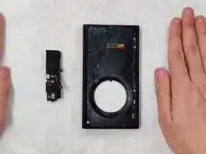
    • The speaker and charging port assembly should then come out easily.

  18. vnMNelySBIXTHqq2
    vnMNelySBIXTHqq2
    aI3odfdvowwchhjo
    HxHfNvCspLZo2ivW
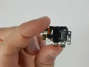
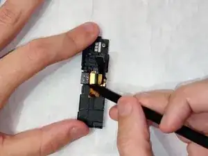
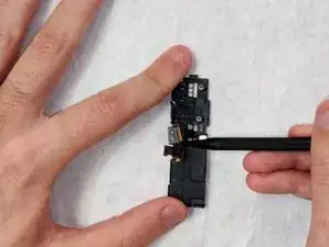
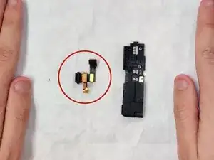
    • Lastly, wedge the spudger on one side of the charging port and push out. Once it is loose, the charging port comes right out!

    • There are clips that you need to get past, so don't be afraid to push a little harder than normal.

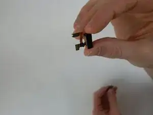
    • The smaller piece from the disassembly is the charging port while the larger piece is the speaker.

Abschluss

To reassemble your device, follow these instructions in reverse order.
Abbi Waterfill

Mitglied seit: 04/11/19

354 Reputation

0 Kommentare