Einleitung

This guide will show you how to replace the speaker in the rear panel

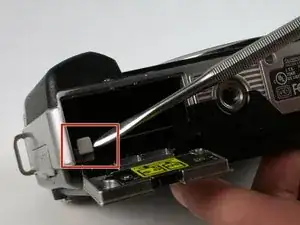
  1. 5S43IkhAEjfIAuIQ
    • Push the gray tab down, using a spudger if necessary, and the battery will come out.

    • Failure to remove the battery prior to disassembly can result in harm.

  2. 5HEMeqWFUrlIfiLl
    5HEMeqWFUrlIfiLl
    Sy2HZRDaDXZTFUC6
    Xk2bikRbFAwSSYKl
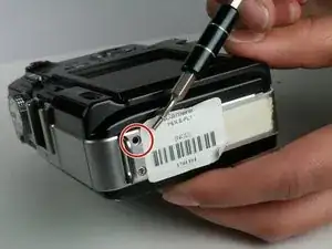
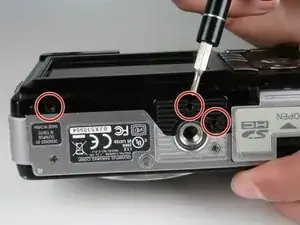
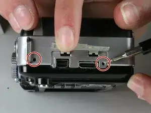
    • There are a total of six screws that must be removed using the the #000 Philips screwdriver.

    • As per picture one: there is one 4.9 mm Philips head screw on the left side of the camera.

    • As per picture two: on the bottom of the camera, there are three 3.4 mm Philips head screws; these are located on the darker area of the case.

    • As per picture three: there are two 5.3 mm Philips head screws on the right side, one is beneath the USB cover.

    Does this method can be applied on Olympus Pen E-P1 Model? Do you have a tutorial like this on that said model I’ve mentioned?

    Matt M -

  3. kWBBCK33yZ6GZnq1
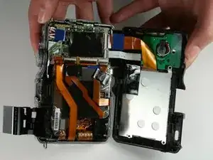
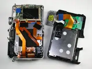
    • Open the case by peeling off the back panel.

    • Pull the case apart gently so that the ribbon connector will not tear.

  4. UpCFtwRfCQsxP5t5
    UpCFtwRfCQsxP5t5
    dphkrwOaWdK3quPT
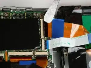
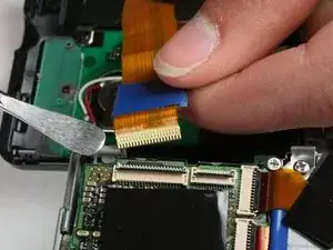
    • Disconnect the two ribbon cables as shown in picture one.

    • Avoid using metal pry tools, as shown in the photo, on internal electronic components, as it can cause a short and damage the device. Use an ESD-safe tool such as a standard nylon spudger.

    • To disconnect a ribbon cable, use a spudger to lift the black tab then pull the ribbon out. This works the same for all ribbon cables.

    The cables (2) on the camera back are quite short. Because of this, removal is quite easy while reconnecting can be challenging. You might have an easier time if you use some masking tape connecting the back to the front loosely to support the back as it takes both hands to reconnect the cables.

    davel4wa -

  5. nSLRJXAPyFS2rUlp
    • The back panel has now been removed.

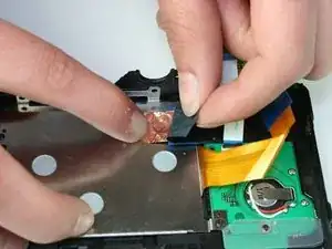
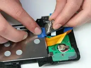
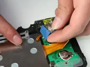
  6. WOiVeTEoWLBqVPxh
    WOiVeTEoWLBqVPxh
    GnPHOuvMQRDk2F4J
    Ds5JPGPXbSwS2eLd
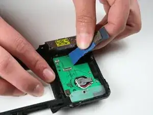
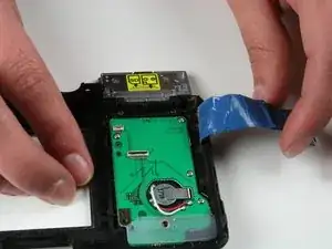
    • As per picture one: peel back the black strip.

    • As per picture two: peel back the Copper strip.

    • As per picture three: peel back the blue tape.

  7. juJlB6gUfQAY4lTW
    juJlB6gUfQAY4lTW
    mfpNQiCF3NJUS2FL
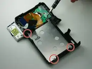
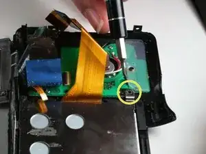
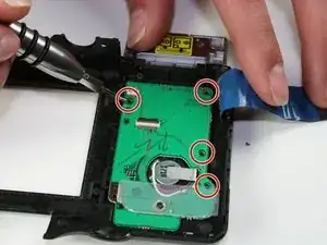
    • There are four screws that need to be removed using the #000 Philips screwdriver.

    • Remove the three 3.4 mm screws on the silver panel.

    • Now remove the 4.3 mm screw located on the green board.

  8. wA6OxrEGYyT6PIKY
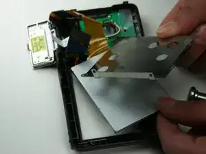
    • Lift out and remove the metal plating over the LCD screen.

  9. FNnAaSoDA3bYWDVY
    FNnAaSoDA3bYWDVY
    lDKXhaITtGX4cKCP
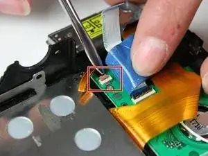
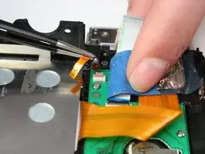
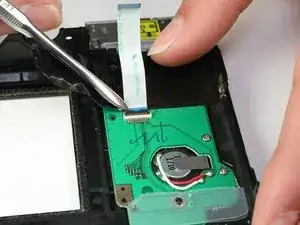
    • Use a spudger to lift the brown lock tab.

    • Avoid using metal pry tools, as shown in the photo, on internal electronic components, as it can cause a short and damage the device. Use an ESD-safe tool such as a standard nylon spudger.

    • Using tweezers, lift the ribbon cable from the brown lock tab.

  10. QuLHWeVqfIDtPLKd
    • Lift out the LCD Screen.

  11. KQqLFKIEOuSFLo1f
    KQqLFKIEOuSFLo1f
    lrBhhTBdSvSm3IIx
    • Using a spudger lift up the black retainer tab.

    • Avoid using metal pry tools, as shown in the photo, on internal electronic components, as it can cause a short and damage the device. Use an ESD-safe tool such as a standard nylon spudger.

    • Gently pull out the ribbon cable.

  12. 5FCyMbLdvGyFdO6V
    5FCyMbLdvGyFdO6V
    CnmWwXp6AL2xCygG
    • Using your fingers, grab the copper grounding strip and blue and black tape.

    • Pull these three back at the same time.

  13. QqZHIIphTUwxUnau
    QqZHIIphTUwxUnau
    dYQky3CydfmLDahf
    • Using a #000 Phillips screwdriver remove the four 3.7 mm screws holding the board.

    • Using a #000 Phillips screwdriver remove the 4.3 mm screw as shown in picture two as well as the clear plastic sheet.

  14. 3RbLEGooJbaXxXJQ
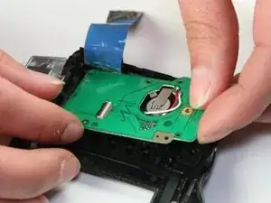
    • Gently lift out the board being careful of the wires in the center

  15. Rd2UEmLwSEPfb14g
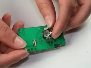
    • With your fingers twist and move the speaker to the other side of the board.

  16. eOZIPPHYHTxQWWGB
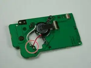
    • Using a soldering iron and soldering wick desolder the two wires connecting the speaker

    • The new speaker must be attached with the wire colors in the same orientation.

    • Solder in the new speaker. Be sure to match the wire color to the original wire placement.

Abschluss

To reassemble your device, follow these instructions in reverse order.

Jeffery Smith

Mitglied seit: 11/03/15

748 Reputation

Ein Kommentar

Dear Jeffery,

thank you very much for this nice tutorial.

Could you please tell us the part number of the speaker you exchanged?

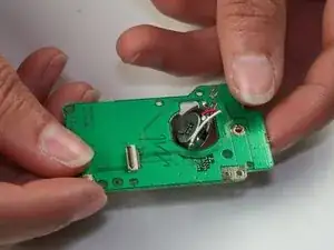
Can’t see the upper part of the number on the pictures: ???1710

Thank you

Sincerely

Lears
Lars Hooge -