Einleitung
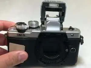
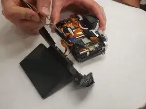
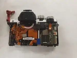
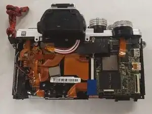
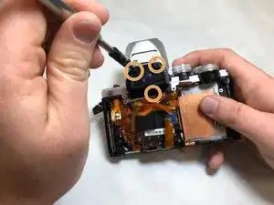
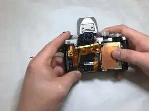
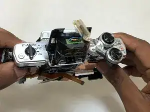
The Olympus OM-D E-M10 Mark II flash replacement will depend on what component of the flash is broken. A soldering iron is required to repair the flash circuitry in every case. If wiring is broken at a point inside the main body of the camera, the camera body's circuitry must be exposed (see Olympus OM-D E-M10 Mark II Motherboard guide).
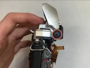
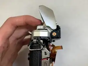
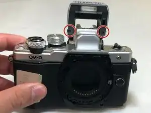
If the issue is in the flash LED then only the silver flash casing needs to be removed. A multimeter is recommended for identification of the area in need of replacement.
Werkzeuge
Ersatzteile
-
-
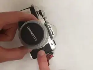
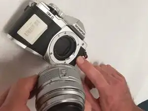
Lay the camera on its back as shown. Using the button located to the right of the lens, hold it down while rotating the lens to release it from the camera.
-
-
-
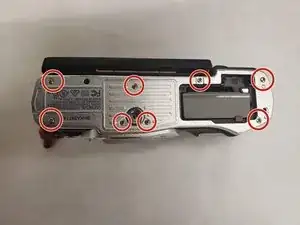
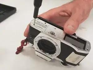
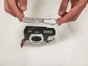
Remove eight screws using a Phillips #00 screwdriver.
-
There are 3 different screws, (2x) 3 mm, (3x) 2.5 mm, (3x) 4 mm.
-
-
-
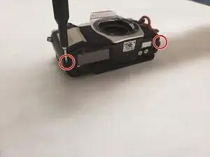
Using the Phillips #00 remove two 5.0 mm screws, one from each side of the base of the camera.
-
-
-
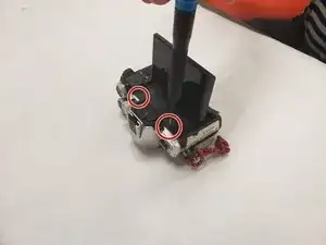
Turn the camera over until it is laying on its backside. Open the screen until it fully extended and perpendicular as shown below. Remove the three screws located there with the Phillips #00.
-
There are two different types of screws. (2x) 2.7 mm, (1x) 3.5 mm.
-
-
-
Turn the camera over on its side as shown. There is a small compartment door that has a screw located underneath it. Remove the 2.5 mm screw with a Phillips #00 screwdriver.
-
-
-
Position the front half as depicted below. The motherboard is the green computer chip on the right half the picture below. You will need to disconnect everything from the motherboard. Gently pull out all orange connectors.
-
-
-
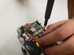
Using a Phillips #00 remove the three 3.0 mm screws while holding the motherboard in place. You should then be able to gently remove the motherboard.
-
-
-
See the Olympus OM -D E-M10 Mark II guide for motherboard replacement and follow the guide until the motherboard is exposed
-
-
-
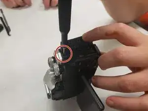
Remove the +/- cover in the center of the dial by levering the small indent.
-
Remove the screw found below the cover.
-
-
-
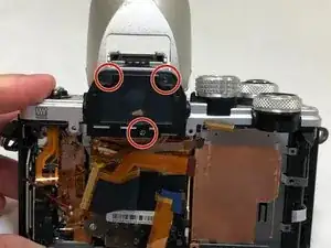
Remove three screws from the front casing of the viewfinder
-
Remove the front casing of the viewfinder, being mindful of any ribbons which may be connected to other components
-
-
-
Remove the two screws on the front of flash component.
-
Remove the outer gray casing of the flash component by using a spudger to separate the black and gray plastic pieces.
-
Use a soldering iron to replace the broken component of the flash connected to the circuit board.
-
To reassemble your device, follow these instructions in reverse order.
