Einleitung

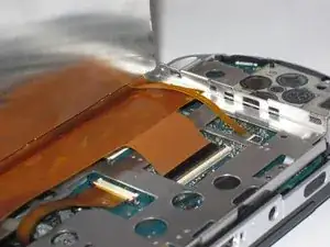
This guide will show you how to remove and replace your PSP speakers.

  1. QacnKmgPd5vO4EVM
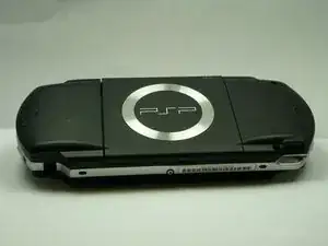
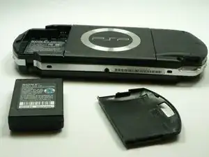
    • Turn the PSP over so its back is facing you.

  2. KfhYCVXbuwocyXOJ
    KfhYCVXbuwocyXOJ
    ET6LQanHrAYARDNK
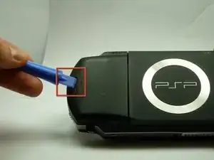
    • Locate the battery casing button on the rear-left side of the PSP.

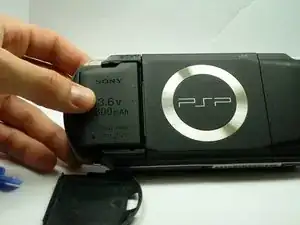
    • Press down the button and remove the battery cover.

  3. ISXv3lrW12xLWbnR
    ISXv3lrW12xLWbnR
    2m4TOHnIVUoYXWUA
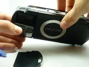
    • Using your finger, remove the battery upwards from the system as shown.

    The use of the opening tool is completely unnecessary. There is a finger actuated opening latch button that says “PUSH” on it. Simply press down with your thumb then slide your thumb down and away, dragining the battery door with it. It will then come off. Assuming the system still has its original plastics, they may have become brittle enough that the opening tool could damage the release button or the plastic cover.

    Franklin Allen -

  4. ckGKHpFUTpAy5N3R
    ckGKHpFUTpAy5N3R
    vJp1HKCLNP1L5iB6
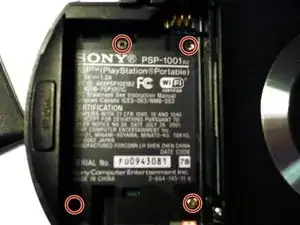
    • Remove the four screws shown with a Phillips #00 screwdriver.

    • You will have to peel back the guarantee sticker to access the screw on the lower left.

    Much luck to you if you have a tiny, metal screwdriver like I did, the screws might be stuck in there and may require some force.

    Squib -

    you need to peel back the warranty sticker in order to access both the lower left and lower left screws

    Frederick zzstu Geib -

    This is a bit misleading, you should only remove the two black screws in the battery compartment. The silver ones can stay.

    Damian Cartwright -

    The two left hand screws won’t come out of mine

    XULF -

    iFixit screwdriver bits aren't thin enough to reach the two screws on the right near the memory stick slot.

    Fliggle_Slaps -

    Can't edit previous comment so here's a new one:

    Standard or older iFixit screwdriver bits aren't thin enough to reach the two screws on the right near the memory stick slot. You'll need precision bits that have longer tips to reach these deep screws.

    Fliggle_Slaps -

  5. aGllC1mxt3FxwjJx
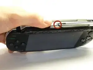
    • Remove the screw from the bottom side of the PSP. Keep it separated from the rest of the screws.

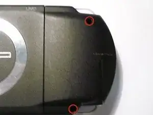
    • Remove screws from back righthand side within the holes.

  6. Ii3a5ygvVCa2DQTW
    Ii3a5ygvVCa2DQTW
    QOKFQYHjjpjkCpkW
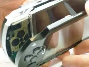
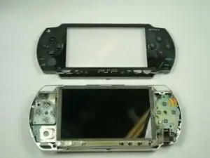
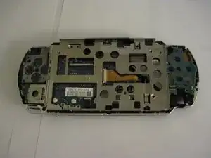
    • Gently separate the outer plastic casing from the rest of the system as shown.

  7. mRetS1vLqaIMHxsm
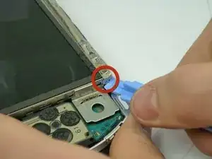
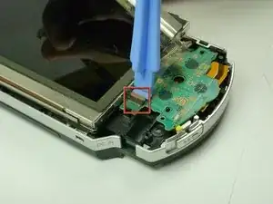
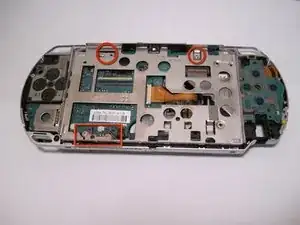
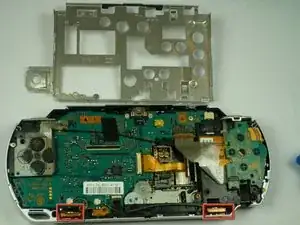
    • The Button Board, at the base of the LCD Screen, is held by two clips.

    • Pry these clips over the nubs using a PSP opening tool. This will release the clips.

    • The Button Board is still attatched to the PSP by a ribbon cable!

  8. XAPlWSPYTBnk4kHW
    XAPlWSPYTBnk4kHW
    y2ZMPu6hFaIMHeEZ
    CM3B1OCMvLaoaYgU
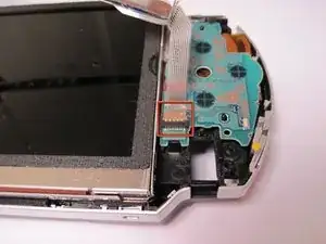
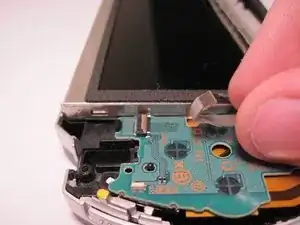
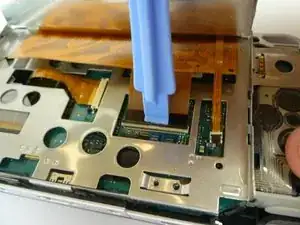
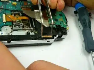
    • The Button Board Ribbon Cable is held down with a latch. Lift the latch open, away from the ribbon cable.

    • Pull the cable away from the latch.

  9. D2bNuCiDSWWwWXII
    D2bNuCiDSWWwWXII
    PWVvGylIhKJX1y1B
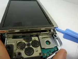
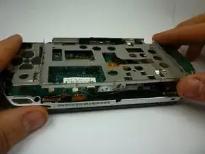
    • The LCD Screen is held by the LCD Frame with similar clips. Slide a thin tool between the clip and the screen and gently pry them apart while beginning to lift the screen.

  10. YPeEx2CAOyTrMhpe
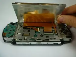
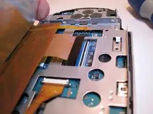
    • The LCD screen is still attached with ribbon cables. Gently lift up the LCD screen so you do not break them.

  11. MfU6sZYZNswQWfrR
    MfU6sZYZNswQWfrR
    haRHpeyReVrZbE3Y
    OVxu3pWnw5aI5CSv
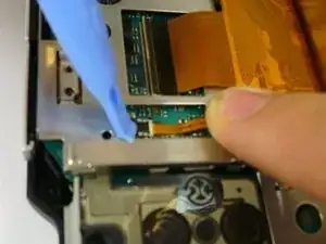
    • The thin Ribbon Cable opens from the opposite side in which the Ribbon Cable enters. Open up the latch towards the Ribbon Cable. The latch will pull up and release the ribbon cable. Put your tool behind the black part, then pry up the black piece of plastic.

    • The wide Ribbon Cable opens from the same side in which the Ribbon Cable attatches, and opens away from the cable.

    • Both of these latches are the black pieces.

    • Gently pull the ribbon cables away from the latches. The LCD screen can now be removed.

    • When reassembling - be careful which way you push the latches. The small one is very easy to break.

  12. 6BQ3cgZuSfpiSfMh
    • Remove the screws on the top and bottom of the frame. Be sure to keep track of where you took each screw out of.

  13. bB5NYrfRtYfQM3X1
    • After the screws are removed, the bottom of the LCD frame will rise.

    • Open up the UMD Drive, and then slide the top of the LCD frame slightly to the right while pulling out.

  14. h4mTdAk1cESASIln
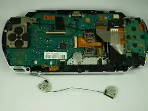
    • The speakers will now be exposed.

  15. GW2bYM5ZyEsMrFPd
    GW2bYM5ZyEsMrFPd
    ywmRMQyakn2CGG4I
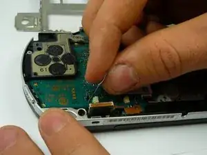
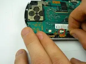
    • The speakers should slide out fairly easily; it may be helpful to use tweezers to begin prying them out.

  16. LOF5CTCxMQJZLE3Z
    LOF5CTCxMQJZLE3Z
    MXpOcwVJFHLFPPvG
    CaIjfwskyKhmFnC3
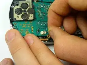
    • Gently unplug the speakers from the socket. The speakers are completely detatched when they are unplugged from the logic board.

Abschluss

To reassemble your device, follow these instructions in reverse order.
Chris

Mitglied seit: 14/01/10

1913 Reputation

0 Kommentare