Einleitung
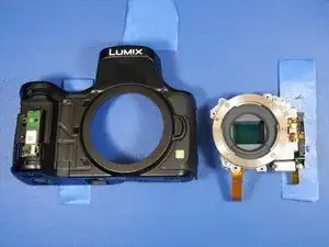
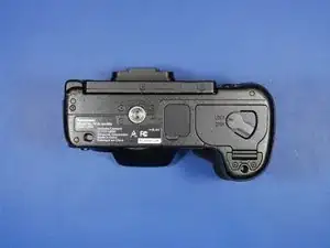
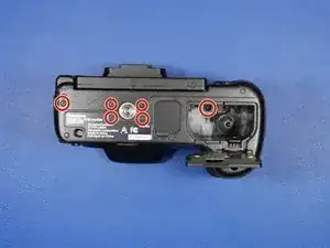
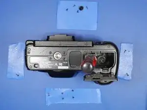
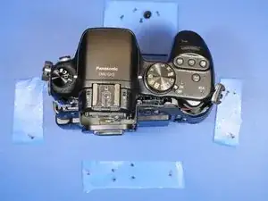
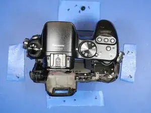
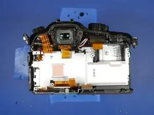
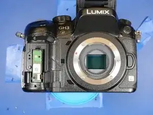
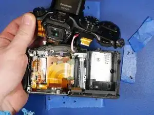
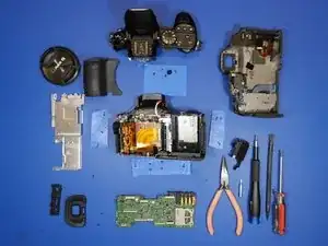
This is a full disassembly guide for the Panasonic Lumix DMC-GH3. Make sure you have the required tools, a bit of patience, and a lot of table space.
Werkzeuge
-
-
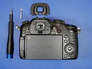
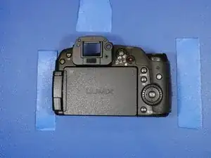
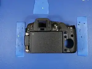
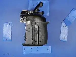
To start the disassembly, place the camera with the lens side down and the back facing you. This camera is assembled in planar layers, so it is best to start from the back.
-
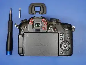
Begin by removing the eyepiece rubber. Slide this part up and it will reveal 5 screws. Remove all of them. Be careful to keep track of the order of these screws and the thread type. Use tape to keep track of the screws.
-
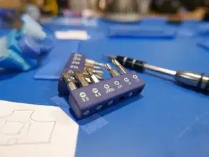
You will need a JIS0 and JIS00 screwdriver and a plastic spudger for this disassembly.
-
-
-
It's important to recognize that this is a camera produced by a Japanese camera manufacturer. The Japanese camera industry loves using JIS (Japanese Industrial Standard) screws over traditional Phillips screws.
-
Although PH#00 will interchange with JIS#00, it is not a perfect fit. Using Phillips can cause more wear on the head of the JIS screws and cause the screws to prematurely strip. If you are in a pinch, just go ahead and use Phillips.
-
Have both JIS#00 and JIS#000 screw drivers available for this teardown. Luckily, both bits are included in the ifixit 64bit kit.
-
-
-
This screw is a bit of a pain to remove as it requires a long shaft screw driver.
-
From here on in, it is strongly recommended to use tape to keep track of the screws as you disassemble the camera. Screws are not always uniform in length or thread type, and some are aluminum, so tape works best here.
-
-
-
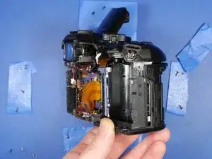
The rear shell of the camera should now be free to slide off the rest of the camera body.
-
Rock the rear shell of the camera from left side to the right side to aid in the removal of the rear LCD shell assembly.
-
-
-
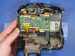
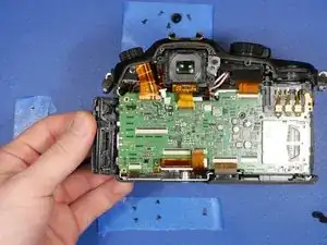
Once the electronics are exposed, it is highly recommended that you remain ESD safe. ESD can fry your precious electronics, and pass thousands of volts through components only rated for a few V DC. ESD can sure ruin your day if you are not careful.
-
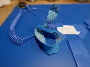
Use an ESD mat and wrist strap, and make sure you are grounded for the remaining of the teardown. Make sure your ESD mat is connected to the ground of a nearby outlet, and make sure your house actually has a ground. Consult an electrician if you are unsure.
-
-
-
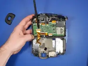
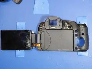
The rear LCD shell can be rotated away from the rest of the shell like a hinge.
-
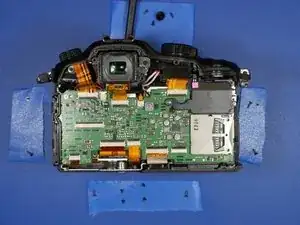
The back LCD and button assembly attached to the main PCB through 2 ribbon cables.
-
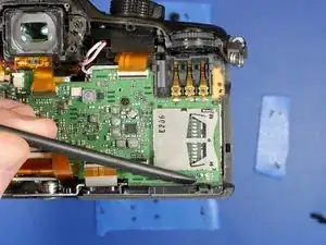
Use a plastic spudger to remove the ribbon cables from the LCD ribbon connectors.
-
-
-
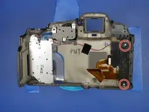
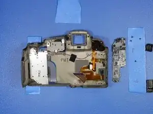
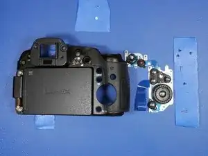
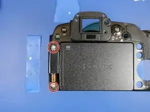
This is the rear shell assembly of the GH3. This contains the LCD sub-assembly buttons and switches.
-
To remove the LCD hinge covers, remove the two screws circled on the right.
-
The hinge covers will simply drop out from the other side.
-
-
-
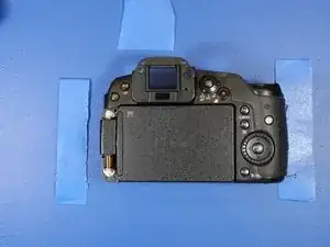
Here's what the rear shell looks like without the LCD hinge covers.
-
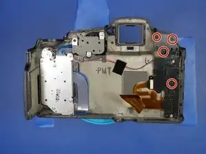
To get further access to the LCD, Remove the 4 screws holding on the plastic cover to the back of the unit.
-
This reveals the ribbon cables from the LCD.
-
-
-
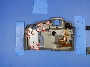
To get further access to the LCD, remove the 2 circled screws.
-
Now the LCD is free from the rear shell. Just be careful snaking the ribbon cables through the shell.
-
-
-
Back to the rest of the camera. With the back LCD shell assembly removed from the body of the camera, It's time to remove the main PCB.
-
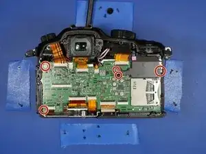
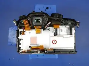
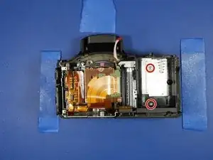
Remove the 5 circled screws. There is a back plastic cover that protects the battery PCB terminals. That should come free once these screws are removed.
-
-
-
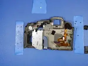
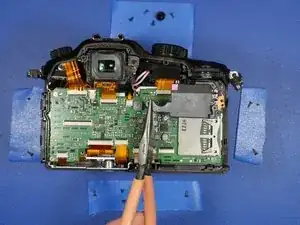
With the cover removed, go ahead and begin removing all the ribbon cables from the PCB. Remove the 2 pin connector as well.
-
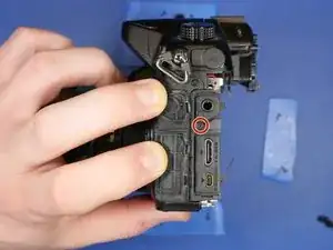
There is one more screw holding in the PCB. Remove the screw on the left hand side of the camera which holds the I/O cover to the PCB.
-
The PCB should now be relatively lose inside the camera.
-
-
-
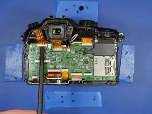
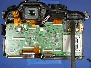
There are 2 black plastic tabs that hold in the PCB. Use a plastic spudger to depress the tabs.
-
The PCB should now come out freely.
-
-
-
The next part of the disassembly involves the removal of the top assembly.
-
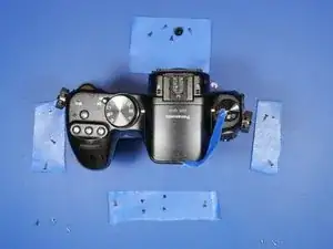
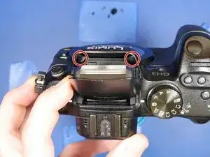
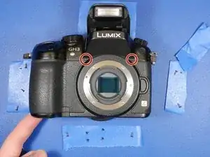
The removal of the top assembly requires you to remove the screws under the pop-up flash unit.
-
-
-
Since the camera is powered off and the battery is removed, the electronically controlled pop-up flash is non-operational. Thus, continuing the repair a bit of a hassle as getting to the two screws is impossible.
-
This means you would have to pop-up the flash before starting the entire diassembly process! This is rather silly, because the pop-up flash gets in the way when disassembling the rest of the camera and it is a delicate assembly.
-
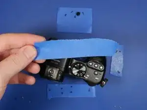
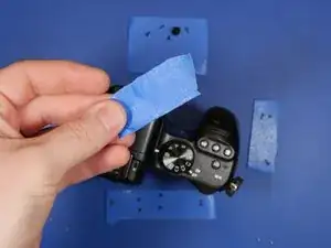
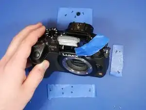
I discovered an easy solution. Take a piece of blue tape, fold it over and shove it between the flash assembly and the shell of the camera.
-
-
-
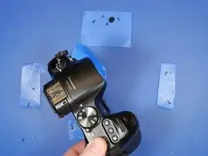
Take this doubled over piece of tape and forcefully shove it toward the back of the flash camera unit. This will trigger the pop-up flash latch release inside the camera and allow you to continue the disassembly without ever needing power!
-
Those two little screws are the culprit! The funny thing is the previous camera, the Lumix GH2, also featured screws here, but the pop-up flash had a manual switch! I guess the designers forgot about this when they implemented an electronic flash trigger switch.
-
-
-
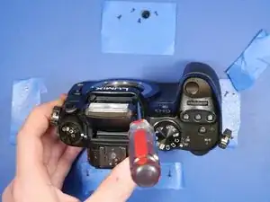
You will need a long shaft JIS screwdriver here too! I didn't have one long enough, so I cheated and used a Phillips to remove these two screws
-
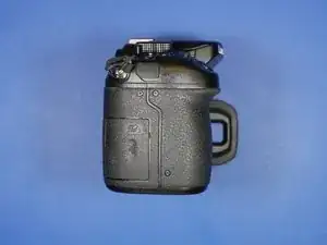
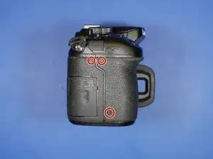
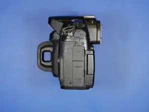
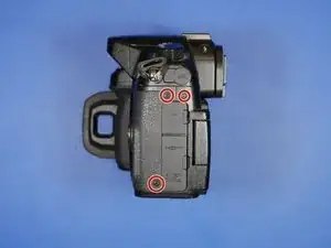
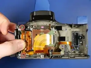
Remove the two screws from the front face of the camera as well.
-
Remove the one screw holding in the aluminum heatsink to the remainder of the camera.
-
-
-
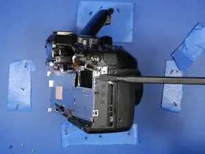
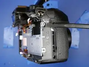
The heatsink is held in on the right hand side by two small clips. Use the spudger fo un-clip the heatsink from the camera.
-
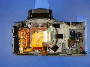
With the heatsink removed, the sensor block assembly is uncovered and the battery compartment is finally unobstructed.
-
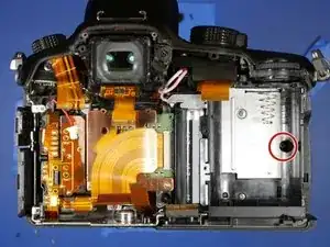
Remove the circled screw from the battery compartment. This screw secures the front grip of the camera to the camera shell.
-
-
-
The grip should now be free and come off the camera easily.
-
Panasonic hid the wifi unit under the grip. This is quite clever since the grip is entirely plastic and electromagnetic waves have little trouble passing through plastic. If they buried the antenna unit further inside the camera, the performance would be greatly hindered by the other metal shelled components.
-
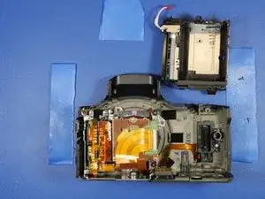
The top unit should now be loose and come free from the camera.
-
-
-
The top unit should be held on only by the flash unit cable. Disconnect this cable and the top unit is now free.
-
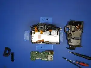
If your workbench is a mess at this point you're heading in the right direction!
-
-
-
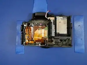
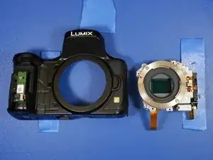
The sensor block assembly, front shell and battery compartment are all that's left of this camera.
-
Let's start with the battery compartment. Remove the two circled screws.
-
The battery compartment should just slide up and out of the camera shell.
-
-
-
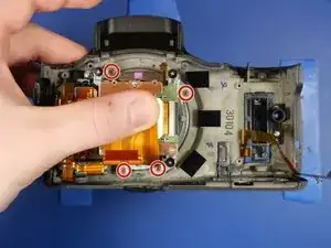
Before removing the sensor block assembly, the sub frame assembly must be removed.
-
Remove the two screws circled. This will provide full access to the sensor block assembly mount screws.
-
To reassemble your device, follow these instructions in reverse order.
4 Kommentare
Very thorough and detailed with lots of needed cautions. I will not attempt this on my GH5 to replace or repair a broken function control knob on my own. This way I have a sense of time needed for a repair and the probable cost be a pro. All for a cheap plastic part they broke off from a minor bump.
Hi merlecole , The GH5 is a similarly disassembly, but the control knob is a relatively straight forward repair. All you need to do is remove the back shell of the camera. You would need to remove the two back ribbon connectors from the front half of the camera which are attached to the main PCB, but that’s the only mildly challenging part. Once the back half is safely removed, its smooth sailing from there. Good luck!
Hi Anthony, very good disassembly instructions thanks. My GH3 has only one problem. The knurled thumbwheel to the right of the viewfinder turns but the switching or potentiometer drags as if grease in it has hardened, or an override clutch has weakened. Do you know if this is a common issue with these? Does repairing it involve a serious stripdown? If so I'm prepared to do it. Best wishes, Tim.
Hi! This is a very easy problem to repair. A lot of gh3 / gh4 control dials skip over time from the friction fit of the rubber dial and the rotating inner plastic dial loosening over time. This is normal because rubber changes over time. In this case, you just need to place a droplet of super glue between the inside of the rubber dial and the rotating plastic groove it sits in. You don't even need to dissemble the camera to repair it. Use your thumb and push the rubber on the dial up to dislodge it from the groove it sits in. You will see a c-channel shaped grove. This is where you want to put the super glue. Grab a sewing needle or pin and a tube of superglue from the store. Any superglue will work. The key is, use a small amount! Squeeze the super glue applicator bottle until a droplet forms on the needle tip. Place this droplet in the c-channel groove I mentioned above. Using a small amount will not overflow the groove so when you push back the rubber part, no glue will spill over and ruin the dial. I have a video of this process I will post soon, probably to youtube.
