Einleitung
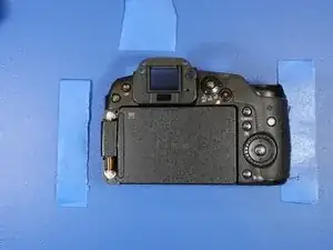
The GH series camera was originally designed to embody a well balanced hybrid camera: one that takes photos just as well as it takes video. This camera series was targeted towards users who wanted the best of both worlds in the convenience of one camera package. Over time, consumers took a liking to this camera series and it became an increasingly common tool used for documentation and even budget film making. I personally took a linking to this camera series due to the value added to my project documentation capabilities.
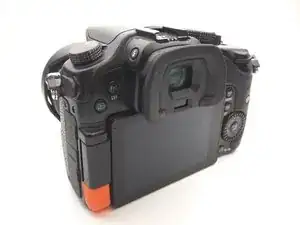
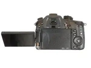
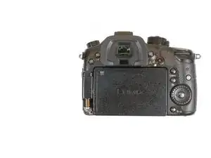
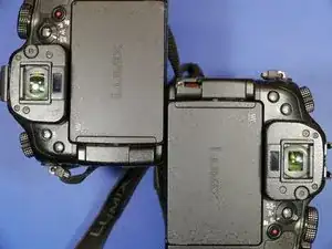
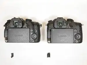
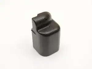
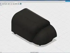
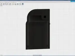
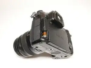
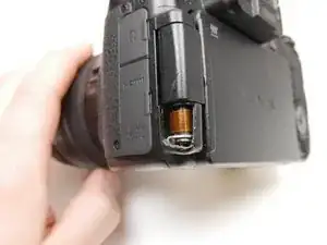
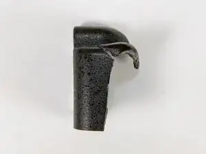
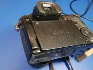
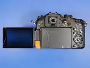
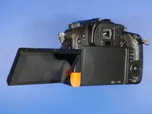
However, of the many GH cameras I've owned, the GH3 and GH4 series cameras gradually developed two very frustrating issues over time. One being the failure of the navigation dials and the other being the failure of the plastic LCD hinge cover. This guide will focus on the replacement of the LCD hinge cover with a redesigned cover that is less susceptible to breaking.
Werkzeuge
-
-
The LCD hinge cover serves a vital purpose: it protects the LCD ribbon cable from the damages of every day use.
-
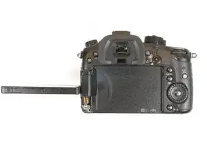
In order to implement a rotating variable angle LCD display into a camera, the LCD needs to be separate from the camera body and be designed as an extremity. In this case, a ribbon cable must be used to pass a real-time low latency display output to the LCD.
-
As you can imagine, the protection of this ribbon cable is paramount to a reliable user interface and continued operation of the camera. So when I found out that I could not buy a replacement hinge cover for my camera, I was quite frustrated.
-
-
-
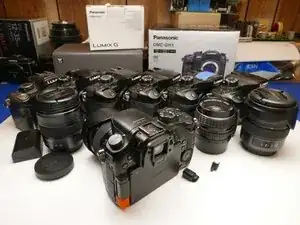
Of the six GH3 cameras and two GH4 cameras I have owned, more than half of the cameras exhibit broken LCD hinge covers. Panasonic heavily reused the design of the Lumix GH3 in the GH4 and many mechanical parts and assemblies are shared between the cameras. The hinge cover is one of them.
-
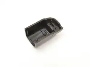
The hinge cover, part # VKM0C55, is not available for sale from Encompass Parts, the dedicated sole supplier of parts for Panasonic consumer cameras. The part is labeled "Restricted Part For Panasonic Use Only."
-
I contacted Encompass about this and they mentioned, "the part that you are requesting has been discontinued and is no longer available through Encompass."
-
I also contacted Encompass earlier in the year and received a similar response.
-
I called Panasonic Customer support and they referred me back to Encompass. I investigated a bit further and called the Panasonic Repair facility in Texas. They refused to sell me the parts and once again referred me back to Encompass.
-
-
-
I can understand that a manufacturer eventually stops producing replacement components and can eventually run out of spare parts.
-
However, the Panasonic Lumix GH4 is still in production, it is still available for sale from genuine suppliers, and has not been discontinued or marked "end of life" by Panasonic.
-
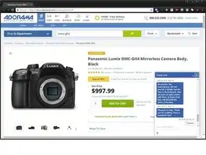
The Lumix GH4 is still available new from B&H and Adorama, two of the largest genuine authorized camera retailers in the USA.
-
Both retailers have confirmed by chat that the Lumix GH4 has not been discontinued as of 5-10-18
-
-
-
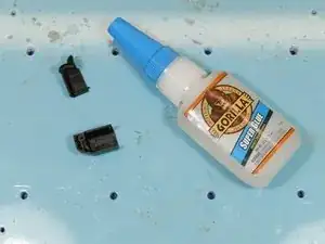
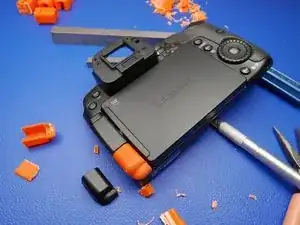
Growing tired of taping over the broken parts or haphazardly gluing them back together, I decided to improve upon the existing LCD hinge cover and redesign the part.
-
-
-
Before I started the modeling process, I decided to take a look at what could be contributing to the failure of the LCD hinge caps.
-
I picked up the camera and put it down a few times. I repeated this on a few surfaces. I noticed that this end cap naturally comes in contact with the table surface.
-
Unless the camera is gracefully placed down after each use, there is no way this end cap would not come in contact with the supporting surface.
-
-
-
Before I begin 3D modeling any part, I like to take the time to fully analyze the exterior construction and overall build of the item. The best way to do this is by looking at the seam lines, feeling around the part and looking for any imperfections.
-
This is not a terribly big part, but the funky geometry could persuade someone to 3D scan the part for ease in modeling.
-
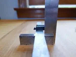
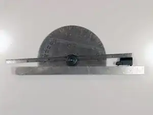
I chose to take a traditional approach and use a trusty pair of calipers, protractor and a set of drill bits. Ideally, one would use a radius gauge set and a pin gauge set, but those tools are quite pricey. The drill bits should suffice.
-
-
-
Picturing the part in my head and analyzing how each geometric shape is created through normal machining operations provides great assistance in the 3D modeling process. This gives me insight into how the part was machined into a mold, injection molded and mass produced.
-
-
-
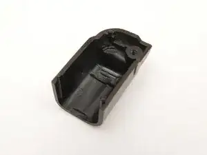
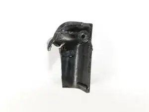
Luckily, one of my broken hinge caps was split down the middle, which offered insight into the wall thickness of the cap at the face of contact.
-
-
-
This cap features very obscure geometry. There are only two faces that are square. Everything else is a compound angle or complex parametric curved surface. In this case, I referenced all my measurements off the two known square sides and measured all complimentary angles accordingly.
-
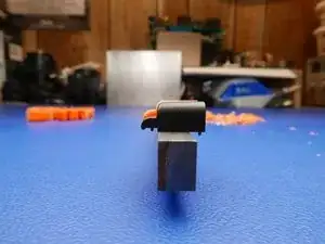
Sometimes this involved using square highspeed tool steel as a reference. The hinge cap has 3 pegs that protrude from the cap. These pegs mate into alignment holes in the face of the back camera shell. Tool steel was used here in order to access the square bottom surface of the part and allow for sound measurements.
-
There were curve balls of course. The bottom of the part was reference horizontal, but the edges orthogonal to that face were not co-linear.
-
Additionally, the top was drafted 2 degrees from the horizontal and the open side was drafted 3 degrees from the Y-axis.
-
-
-
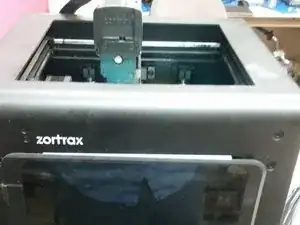
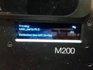
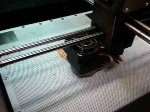
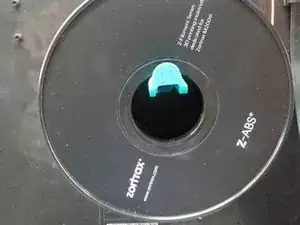
After triple checking my CAD, I went ahead and tested my design on a 3D printer. I used a Zortrax M200 3D Printer. This is an FDM (Fused Deposition Modeling) printer designed to print parts out of a filament material. In this case ABS (Acrylonitrile Butadiene Styrene), was used for the print.
-
-
-
ABS plastic was chosen for the prints because of its durability and ease of availability. For these parts, I am using an orange pigment ABS plastic. UV stabilized ABS filament would be a great candidate for this print but it was not available at the time of print.
-
An SLA (Stereolithography) 3D printer is not ideal in this case because this is a thin walled part (<1mm wall thickness) that may be exposed to extended outdoor use. UV curable resin is not very tolerant of excess external UV radiation and the material properties of the resin can change over time with additional UV light.
-
UV curable resin is also susceptible to creep and can discolor, which is not desirable for a replacement camera part.
-
-
-
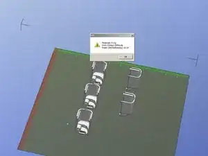
UP Visual 3D was used to place the components on the build platform and optimize part build time.
-
-
-
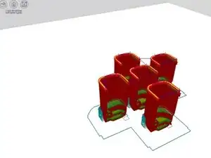
Cura Typa A was used as an infill generator and generated the build surface for creating the parts.
-
Cura also converted the .STL file into a native G code for the Zortrax 3D printer.
-
-
-
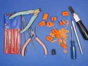
Cleaning up these parts turned out to be more of a chore than usual. These parts are a bit more delicate than the larger 3D prints I am used to. This is due to how close the wall thickness was to the thickness of the support material.
-
The part texture of FDM is no where near that of SLA, so a bit of sanding was required to get a nice smooth finish.
-
-
-
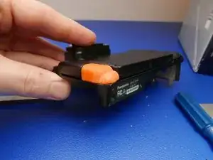
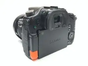
The fit on these replacement parts was quite remarkable for the complexity of the part. The orange serves as a good contrast to the rest of the camera too.
-
The screw hole on the part turned out to be the perfect size and the cap seems to hold on similarly to the genuine Panasonic hinge caps.
-
-
-
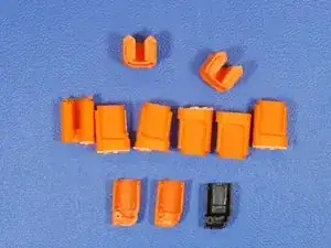
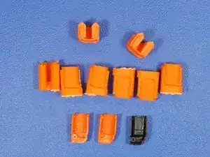
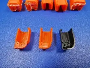
Six parts were printed to serve as examples of minor part design iterations. This was intentional in case I made an error in measurement. Four additional prints were made as extras in case the parts were damaged during cleanup.
-
A good way to keep track of different part iterations is to engrave revision letters or numbers into the part printed. In this case, I embedded the label into the bottom of the cap where it would not be seen.
-
S = stepped geometry on cut 16
-
W = Wider semicircle on cut 17
-
N = Notched length on cut 11
-
-
-
Since I modeled an entire copy of the Panasonic hinge cap in CAD, I decided to take the time and improve on the design with my own iteration.
-
The new design improves upon the Panasonic design in three ways.
-
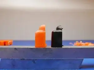
The 2 degree body draft angle was removed, allowing for a more square profile and thicker walls. This reduces the chance of vertical shear lines forming into cracks.
-
The stepped geometry inside the OEM cap designated for hinge clearance was removed since the draft angle no longer brought the cap wall in contact with the hinge.
-
The screw hole fill was increased and the previously ribbed geometry around the hole was completely filled. This reduces the chance of hole tear-out when the cap is removed several times.
-
-
-
When improving upon an existing design, take the time to thoroughly inspect and gather as much information as possible about the broken part.
-
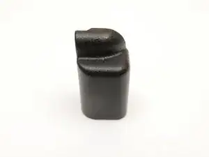
Looking closer at the broken OEM end cap, you can see an external random texture. Such random textures are common on high-content glass reinforced plastic parts such as those used in power drills.
-
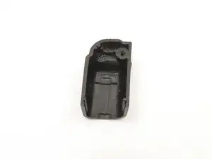
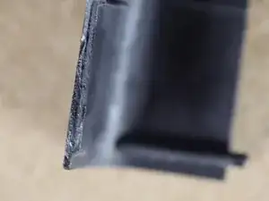
On close inspection, the fracture line reveals that the part is not actually glass reinforced. The texture is also absent on the inside walls of the part and there are no plastic designations or stamps on the inside walls.
-
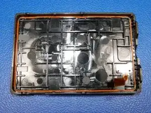
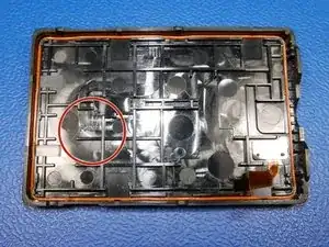
The circles on the inside of the part also reveal that the part was indeed injection molded.
-
-
-
To get a better idea of the types of plastics used in the camera, I took apart the neighboring LCD and checked the other end cap. While the other end cap was bare, the inside of the LCD shell revealed that the part is indeed ABS plastic.
-
The LCD shell is not just ABS plastic but PC+ABS plastic. This material property is the last barrier of entry towards making an excellent repair part.
-
-
-
With this last shred of information, it's a good time to step back and think about how this part was actually produced.
-
This end cap, like all the other parts of this camera, was designed in a Computer Aided Design (CAD) package by mechanical, electrical, material and systems integration engineers. Prototypes were produced and parts were iterated to create a more polished end product.
-
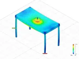
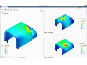
Along the design process, various Computer Aided Engineering (CAE) simulations may have been run on the parts and assemblies to ensure proper fit, ease of manufacture and endurance. Finite Element Analysis (FEA) and Computational Fluid Dynamics (CFD) are two of the most popular CAE tools in use today.
-
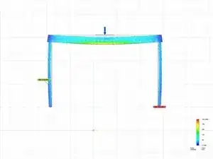
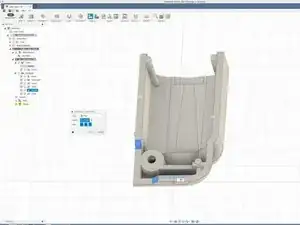
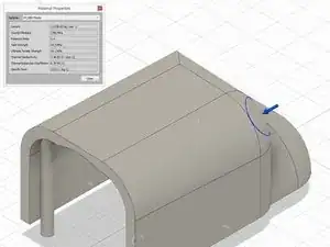
Autodesk Fusion 360 will be used to demonstrate FEA for this project.
-
-
-
FEA is a numerical modeling tool used for the prediction of how a part or assembly behaves under specific loading conditions.
-
FEA involves the summation of finite elements by the finite element method. Finite elements can be thought of as small regions broken down from the original part to ease in calculations.
-
The finite element method takes a numerical approach toward an approximate solution of partial differential equations. The individual finite elements represent an approximation of a partial differential equation used to solve a specific boundary condition.
-
These finite elements are summated through the body of a part and are represented as a mesh of polygons. The end result is a more usable set of simultaneous algebraic equations which can be more easily manipulated to a desired result.
-
Why all this emphasis on mathematical theory? Having a greater understanding of how FEA works allows the designer to have a better idea of how to read and interpret the FEA results. This allows for greater part optimization and allocation of material to satisfy loading conditions, making FEA a fantastic and invaluable tool in a designers' toolbelt.
-
-
-
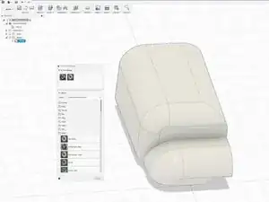
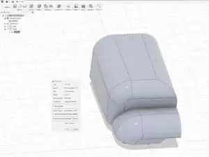
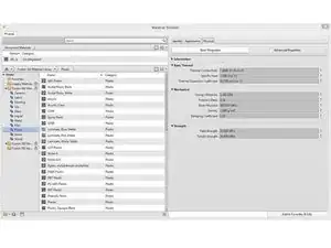
A good way to prepare for any simulation work is to make sure the material properties are correct for the modeled part.
-
In the "Model" work space, right click the body from the bodies tree. Select physical material.
-
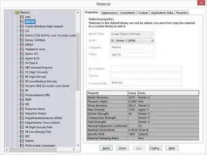
Select PC/ABS plastic from the included fusion360 plastic library
-
To verify the material, right click the body in the materials tree and select properties. Under Physical material is should say PC/ABS plastic.
-
-
-
Switch the workspace over to simulation and let the experiments begin.
-
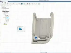
Before you slam that solve button, make sure you have all your constraints covered and loads specified.
-
In this case, the main screw should be constrained in XYZ axis, the flat sides that mate flush to the camera body should be treated as frictionless, the two circular pegs should be constrained in just the XY axis and the square peg should be constrained in the XY axis.
-
There are additional supports that must be constrained as well, specifically the 45deg angled side walls that aid in rotational restriction of the end cap on the camera.
-
Next up is the definition of the load. F = m*a is an equation synonymous with Force in Newtonian mechanics. Newton is the SI unit for force. Mass is in kilograms and acceleration is in meters/sec^2. F = m*a with mass equal to the weight of the camera and g = the gravitational constant, 9.8m/s^2.
-
The force on the front face of the end cap is declared at a 30 degree angle to the orthogonal. This is reasonable considering the way the end cap would contact with a normal surface.
-
Weights: GH3+battery = 550g, GH3+battery+12-35mm lens = 810g, GH4+battery = 560g
-
-
-
Here's some general guidelines to follow for FEA simulations:
-
Sharp internal corners may cause inaccurate results
-
The finer the mesh of polygons, the greater the accuracy of your results
-
Minimum safety factor of 3 is recommended for designs. Shoot for 2x yield strength at least. The red zone signified the yield strength of the material has been reached and the part has failed.
-
Static stress studies are not ideal for materials with higher elasticity, such as rubber and plastic.
-
Static testing does not consider damping or inertial effects, such as momentum.
-
Stresses should not exceed yield-strength of material.
-
Load must cause deflections or rotations in the item under test.
-
-
-
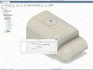
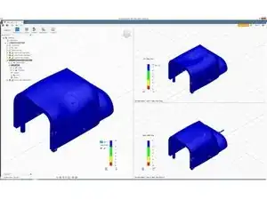
The part should be all ready for simulation and the pre-check list should have a green check next to it. Hit solve at the middle of the top of the page to see the results.
-
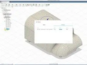
There are 2 options for solving: on the cloud or locally. Local solving is free, but cloud simulation involves cloud credits, which are not free. Autodesk provides 300 free starter cloud credits though.
-
-
-
Why did this simulation pass? Was the part designed right all along or was it simply user abuse that caused it to fail? The answer is more complicated than it seems.
-
Of course the force on the end cap will vary depending on the mass of the entire body and the angle of impact incidence. I chose the 3 most common areas of impact based on the most abused GH3 end cap I could find.
-
In this case the type of plastic plays an important role in discovering the failure mode of the part. PC-ABS is a blend of Polycarbonate(PC) and ABS and varies based on PC:ABS concentration, recycled content concentration, quality of recycled content and manufacturer preferences.
-
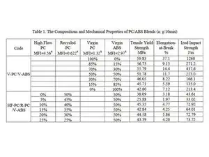
Overall, a pure PC-ABS blend has a greater tensile strength than pure ABS and shares a similar high-strength and high impact resistance common to PC. According to the research paper Processing and Characterization Of Recycled Pc/Abs Blends with High Recycle Content, the yield strength of 50:50 pure PC:ABS is 51.78MPa while pure abs alone is 42.8MPa.
-
The stock yield strength of PC-ABS provided with Fusion360 is 54.4MPa. This would put the fusion360 PC-ABS on par with the 70:30 pure PC:ABS yield strength included in the study.
-
-
-
There is a good chance that this part is composed of partially recycled plastics, considering Panasonic's goal of increasing reuse of resins and other materials.
-
Unfortunately, significant reductions in mechanical properties occur after replacing virgin PC by recycled PC in the PC:ABS mixture. The Izod Impact strength drops off sharply once recycled PC is substituted into the PC-ABS blend, according to the linked research.
-
A 50:50 blend of recycledPC:ABS results in a 43.61 J/m impact strength, while a 50:50 pure PC-ABS blend has an impact strength of 253 J/m, 5.8x stronger. A table copied from the referenced study is included here for convenience.
-
Taking this information into account, it makes sense that the part did not fail FEA simulation. The included material properties did not accurately represent the part and the impact resistance and tensile strength of the analyzed part far exceeded the properties of a recycled PC:ABS part.
-
-
-
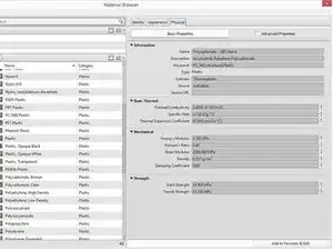
To add even more variability to the simulation, the declared values for PC-ABS differ from CAD package library to CAD package library. The solidworks PC-ABS and fusion360 PC-ABS material properties are 54.4 MPa and 40MPa for yield strength, respectively. The stated shear modulus is 862.2MPa and 2300MPa, respectively. This is quite a departure.
-
-
-
Time to determine reasonable material characteristics for the end cap. 20-30% recycled plastic seems to be the norm for companies who make efforts to implement recycled materials so a 30:70 ratio of recycledPC:ABS seems like a decent conclusion based on these criteria.
-
Using data from fusion 360, solidworks, the first research pdf, this stratasys pdf, and another research article, I was able to roughly estimate material properties for this end cap.
-
These are the values I used under simulation: Young's Modulus: 2.6 GPa, Poisson's Ratio: 0.40, Shear Modulus: 1000MPa, Density: 1.1/cm^3, Yield Strength: 44.58 MPa, Tensile Strength: 46MPa
-
Young's modulus, Poisson's ratio and the density were largely the same between different sources for PC:ABS. The yield strength was used from table 1 in the first research pdf to match the 30:70 blend. The tensile strength was estimated to be 46MPa as the tensile strength of similar material concentrations was slightly higher than Yield.
-
Remember, these numbers are not absolute. There are many different variations of PC-ABS and there do not seem to be any standardized set of blends to follow. There are also batch-to-batch variations in the properties of recycled polymers because of variability in the source and the composition of recycled material streams.
-
Besides this, modifiers can be added to the PC:ABS blend to add desired mechanical qualities to the resulting material or help in binding. This allows for yet even more PC-ABS material variations.
-
-
-
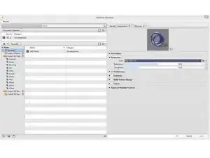
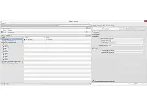
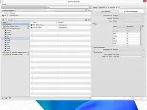
In order to test drive these new values, you will need to make a custom material. Back in the fusion360 simulation workspace, go to materials > manage physical materials. Select ABS plastic. Add to my favorites. In the favorites you will now see ABS plastic. This is your custom new ABS plastic.
-
Right click this and rename to "PC-ABS custom" plastic. Double click to change the properties. Since you will be modifying the material properties of the ABS plastic template, choose a different color for the appearance for your new PC-ABS.
-
This helps to differentiate it from the stock fusion360 pc-abs plastic and makes it easier to verify that you have selected the correct pc-ABS plastic for your part.
-
-
-
This time, instead of just running a static stress analysis, an event simulation will be run as well. If the part is indeed a mixture of recycled PC and ABS, the part will likely still pass a static analysis, but fail under repeated impact testing.
-
Thus, the part may be able to endure impact and rough handling, but continued exposure to impact damage can lead to sustained damage and eventual failure. This follows with the lower Izod impact strength that recycled blends exhibit.
-
As expected, the part passes the static stress test, with slightly less of a safety factor than the stock fusion360 values for PC:ABS.
-
-
-
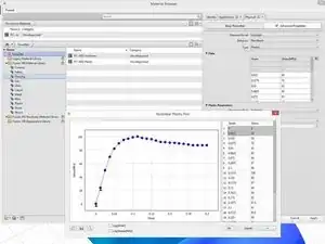
In order for the event simulation to make any sense, the PC-ABS needs to be modeled as a non-linear material. The best way to do this is to duplicate the custom PC-ABS material in the favorites and change the advanced properties to plastic.
-
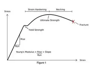
This allows for calculations to take place past the elastic limit of the material (point of yield strength) and into the region of plastic deformation. The plastic deformation region of the material represents the range in which the material endures unrecoverable change to its structure past the point of recovery.
-
-
-
The non-linear simulation worked! It shows that the end cap does indeed endure plastic deformation from the continued exposure to random impacts.
-
Suggestions for future improvements would be to add an impact modifier to their PC:ABS blend for future end cap designs, use a slightly lower recycled PC content in their blend or just increase the wall thickness of the part.
-
-
-
One of the most critical aspects of redesigning a part is ensuring compatibility. Ideally, the redesigned part should not cause any damage or unforeseen consequences to the functionality of the item being repaired.
-
In this case, the cap was tested to ensure the proper rotation and swing of the LCD assembly without causing any issues in clearance with the other parts of the hinge.
-
After continued use, there were no evident marks of part interference or rubbing.
-
-
-
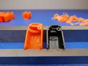
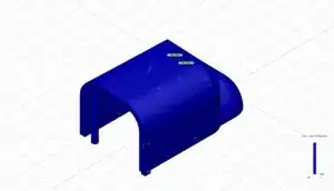
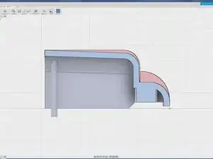
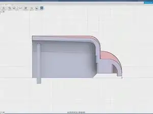
To represent the changes in design, here's a cap cutaway on the exact model of the Lumix GH3 end cap and my newly revised design.
-
The blue zebra cross section represents a cross section of the OEM Lumix hinge cap.
-
The red zebra cross section represents a cross section of my thick walled end cap.
-
The cross sectional thickness of the walls on my end cap are 0.4in thick, where as the measured cross sectional thickness of the OEM lumix end cap is 0.0365in
-
Three .STL files are attached to this guide.
-
"lumix cap square R2" represents a square profile end cap with the same wall thickness as the OEM lumix end cap for greatest chance of compatibility across GH3 & GH4 cameras. This is the most tested end cap design. This is the best file to download as it should fit within the accepted assembly tolerances followed by Panasonic.
-
"lumix cap beefy R3" represents a square profile end cap with thicker walls for greatest durability. This may not fit all GH3 & GH4 cameras due to natural variation in assembly tolerances between batches of cameras.
-
"lumix cap identical R2" represents an end cap as close to the original OEM end cap as possible.
-
-
-
The replacement process for the newly designed hinge cap is exactly the same as the genuine one.
-
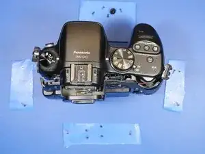
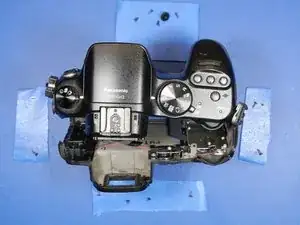
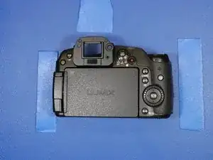
To start the disassembly, place the camera with the lens side down and the back facing you. This camera is assembled in planar layers, so it is best to start from the back.
-
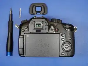
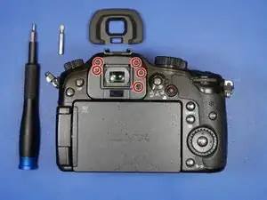
Begin by removing the eyepiece rubber. Slide this part up and it will reveal 5 screws. Remove all of them. Be careful to keep track of the order of these screws and the thread type. Use tape to keep track of the screws.
-
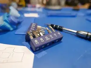
You will need a JIS0 and JIS00 screwdriver and a plastic spudger for this disassembly.
-
-
-
It's important to recognize that this is a camera produced by a Japanese camera manufacturer. The Japanese camera industry loves using JIS (Japanese Industrial Standard) screws over traditional Phillips screws.
-
Although PH#00 will interchange with JIS#00, it is not a perfect fit. Using Phillips can cause more wear on the head of the JIS screws and cause the screws to prematurely strip. If you are in a pinch, just go ahead and use Phillips.
-
Have both JIS#00 and JIS#000 screw drivers available for this teardown. Luckily, both bits are included in the ifixit 64bit kit.
-
-
-
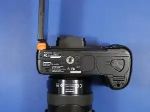
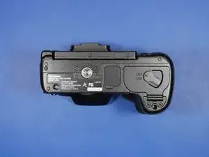
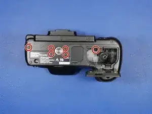
There are 6 screws on the bottom of the camera. One is hidden in the battery compartment.
-
-
-
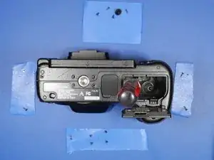
This screw is a bit of a pain to remove as it requires a long shaft screw driver.
-
From here on in, it is strongly recommended to use tape to keep track of the screws as you disassemble the camera. Screws are not always uniform in length or thread type, and some are aluminum, so tape works best here.
-
-
-
The rear shell of the camera should now be free to slide off the rest of the camera body.
-
Rock the rear shell of the camera from left side to the right side to aid in the removal of the rear LCD shell assembly.
-
-
-
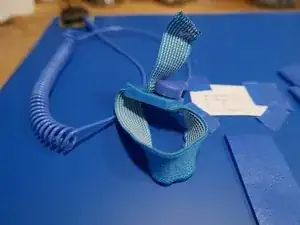
Once the electronics are exposed, it is highly recommended that you remain ESD safe. ESD can fry your precious electronics, and pass thousands of volts through components only rated for a few V DC. ESD can sure ruin your day if you are not careful.
-
Use an ESD mat and wrist strap, and make sure you are grounded for the remaining of the teardown. Make sure your ESD mat is connected to the ground of a nearby outlet, and make sure your house actually has a ground. Consult an electrician if you are unsure.
-
-
-
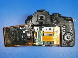
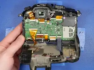
The rear LCD shell can be rotated away from the rest of the shell like a hinge.
-
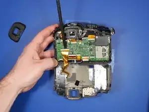
The back LCD and button assembly attached to the main PCB through 2 ribbon cables.
-
Use a plastic spudger to remove the ribbon cables from the LCD ribbon connectors.
-
-
-
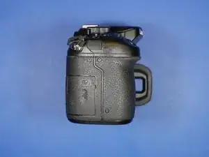
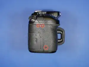
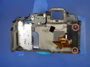
This is the rear shell assembly of the GH3. This contains the LCD sub-assembly buttons and switches.
-
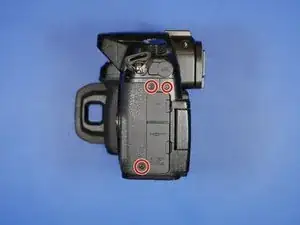
To remove the LCD hinge covers, remove the two screws circled on the right.
-
The hinge covers will simply drop out from the other side.
-
-
-
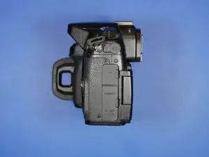
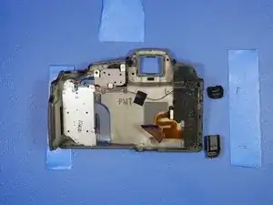
Here's what the rear shell looks like without the LCD hinge covers.
-
Go ahead and install the new bottom hinge cover and remember to reinstall the original top cover and you're ready to go.
-
-
-
How do I feel about this Panasonic camera part fiasco? Will I buy another GH series camera in the future?
-
I already repaired a DMW-XLR1 sound adapter for a Lumix GH5, but I have held off on purchasing a new GH5 camera due to how Panasonic handles consumer spare parts.
-
It looks like the GH5 has it's own set of mechanical problems and still shares the same dial problem as the GH4 and GH3, so I think I'll hold out a little bit longer.
-
This repair will allow me to continue using my GH3 and GH4 cameras well into the foreseeable future and will enable more documentation of personal projects on ifixit and salvagedcircuitry.
-
To reassemble your device, follow these instructions in reverse order.
4 Kommentare
Thank you for such a through and educational guide. I benefited from your design by just getting the part printed, but I appreciate all the thought and considerations in designing the replacement part.
Excellent! I’m glad you were able to get your camera back to like-new condition again :D
Hi there
Thus is amazing and please how much do you charge if I need mine done please and can you give me your contact details for thus please .
Hi Francis, The files needed to print an end cap are all in the article! If you have a friend with a 3d printer, and a screwdriver, that's all you need to get the job done. Try it yourself! Good luck!
