Einleitung
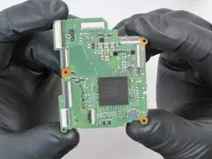
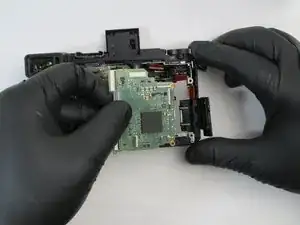
The Main PCB is one of the most important parts of the Panasonic Lumix DMC-GX85; it cannot function properly without one. Replacing a faulty Main PCB is made easy here.
Werkzeuge
-
-
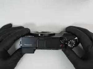
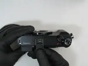
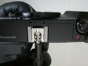
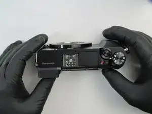
Using a spudger, gently lift the forward end of the shoe spring to disengage its locking mechanism.
-
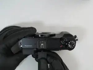
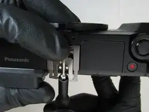
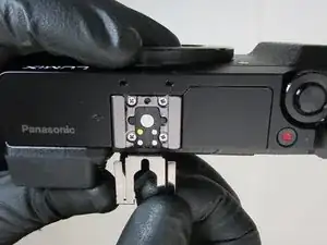
While holding the forward end of the shoe spring up, push from its lifted end to remove the shoe spring.
-
-
-
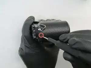
Turn the camera so the side with the jack cover is facing you.
-
Near the camera's top end, remove the 4.0mm black Phillips #0 screw on the bottom in this orientation.
-
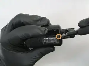
Open the jack cover and remove the 4.0mm black Phillips #0 screw inside.
-
-
-
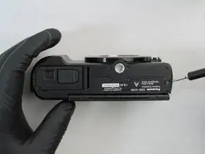
Flip the camera upside down so the bottom of the camera is facing you.
-
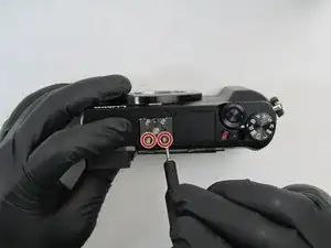
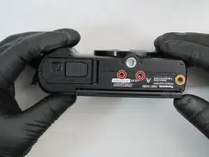
Remove the two center 2.5mm black Phillips #0 screws.
-
Remove the outer 4.5mm black Phillips #0 screw.
-
-
-
Turn the camera so the display screen is facing you.
-
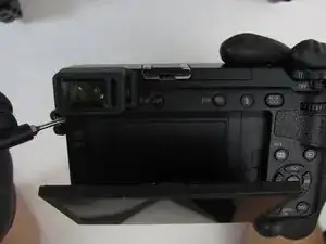
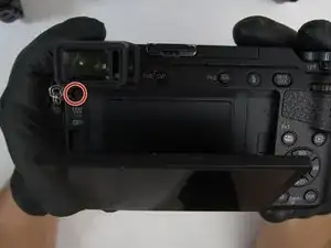
Rotate the top of the screen away from the camera body to access and remove the 4.5mm black Phillips #0 screw.
-
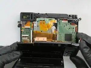
Remove the rear camera cover by gently pulling from the top side.
-
-
-
Turn the camera so the lens is facing down with the rear cover pulled back.
-
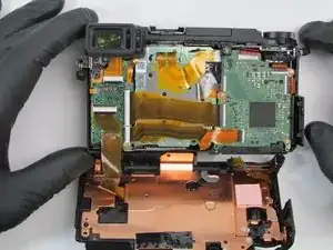
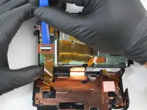
Disconnect the ribbon cable from the camera by pulling up on the black locking tab with an iFixit opening tool.
-
Pull the ribbon cable from the connector. The rear cover is now completely detached from the camera.
-
-
-
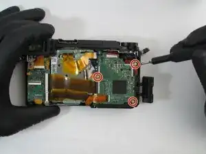
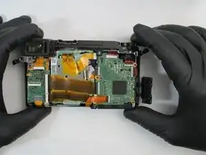
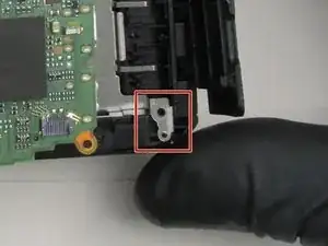
Remove the three 3.5mm silver Phillips #0 screws mounting the main PCB to the camera frame.
-
-
-
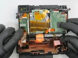
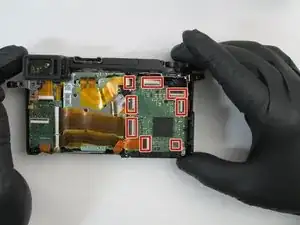
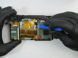
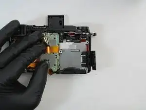
Disconnect the eight ribbon cables from the main PCB by pulling up on the black locking tabs with an iFixit opening tool.
-
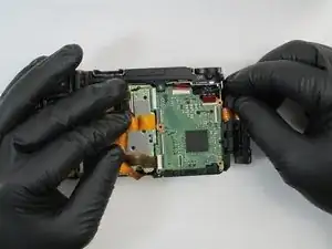
Pull the ribbon cables from the connectors.
-
To reassemble your device, follow these instructions in reverse order.
Ein Kommentar
Good day. How do I get the board both of the, the one on the right and one on d left
Tobas -
