Einleitung

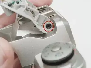
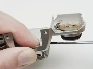
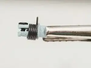
One common failure of the ZX-5n is the pop up flash. The pivot holding the spring can break relieving the tension on the spring. When this happens, the flash will no longer pop up to its proper position. It may be possible to repair the existing part with epoxy but you can also replace it with a donor part from another camera or with a 3D printed part. A model for the 3D printed part can be found in the Documents section of the Pentax ZX-5n page.

  1. lgs2BFmwctNUvEEY
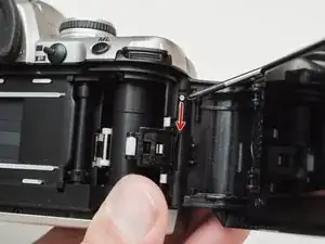
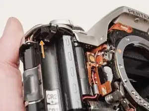
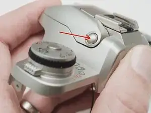
    • Push down on the screw to depress the spring loaded hinge and release the door.

  2. xqMOa4QfTrEMSjLQ
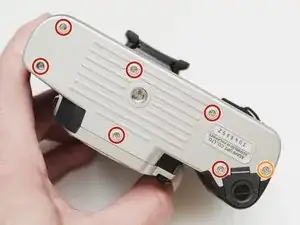
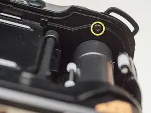
    • Remove six 5.3 mm #00 screws.

    • Remove one 3.4 mm #00 screw.

    • The short screw has a machine thread and screws into the plate underneath. The rest screw into the plastic body.

  3. JBNm1gvrrVIsOnvC
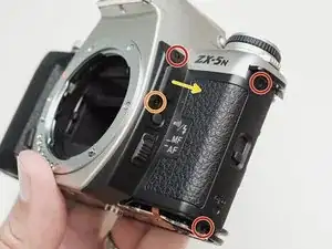
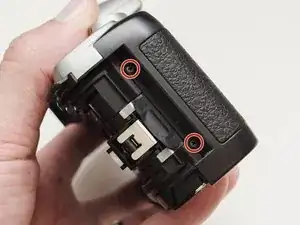
    • Remove three 5.3 mm #00 screws (the bottom-most screw is not always present).

    • Remove one 7.3 mm #00 screw.

    • Remove the remote trigger cover.

  4. kaurbKcGc3sICMvp
    kaurbKcGc3sICMvp
    qAMWaUYPEdKSqKBQ
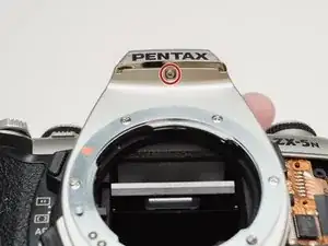
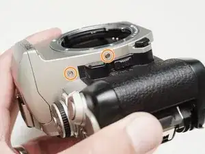
    • Remove one 3.4 mm #00 screw.

    • Remove two 5.3 mm #00 screw.

    • Gently lift up on the flash housing to help remove the cover if necessary.

  5. XTT2gETZspMWvdLW
    • Remove two 3.9 mm #00 screws.

  6. 3my2vQuEkTFMiy1K
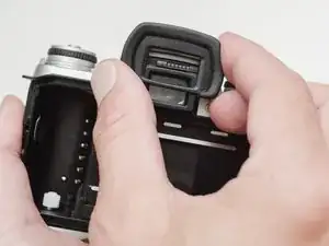
    • Slide the eye cup up and off to access the screws underneath.

  7. e53TOwaDpAgeyAD6
    e53TOwaDpAgeyAD6
    OJJ5WDhEjPdLrFAa
    XYapgMENQtcSAZZH
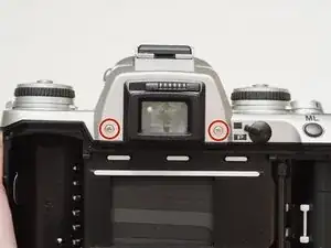
    • Remove two 5.3 mm #00 screws by the eyepiece.

    • Remove one 6.8 mm #00 screw in the battery compartment.

    • Remove one 7.0 mm #00 screw near the take up spool.

  8. htpX4AygbXbvTyuw
    • Lift the cover so it is just free of the body. It is still attached by several wires.

  9. cEB6KP4SjU3TTSop
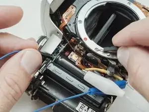
    • Use a 1kΩ-10kΩ resistor to discharge the capacitor. Place the resistor between the blue wire, exposed in the previous step, and ground.

    • The flash capacitors store energy at a very high voltage. Failing to discharge the capacitors properly could result in personal injury and/or damage to the camera.

  10. AVjBYR4r3hgfCPW3
    AVjBYR4r3hgfCPW3
    mwwUN2MAswgLKGJM
    PZKqtlcJpPrdVVJ6
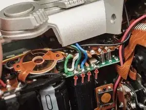
    • De-solder the green, blue, brown and black wires from the flash PCB.

    • De-solder the black wire.

    • Pull the black wire out until it is completely free from the body of the camera.

  11. uQaeAvoVew1fHMKa
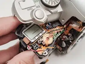
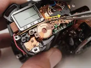
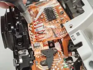
    • Desolder the flex cable connecting the top plate to the camera body.

    • Be careful not to overheat the flex circuit. Work in short durations. Allow for cool downs in between if necessary.

  12. OI5QBlGNWcEKJnjL
    • Push the release button to pop up the flash.

  13. YQ11PwLqQmBgUiyw
    YQ11PwLqQmBgUiyw
    kFWLtLFKuCKyqLEE
    vcP4gNBWatv3Uct1
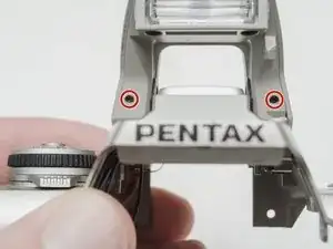
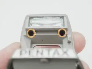
    • Remove two 2.9mm #000 screws.

    • Remove two 4.4 mm #00 screws.

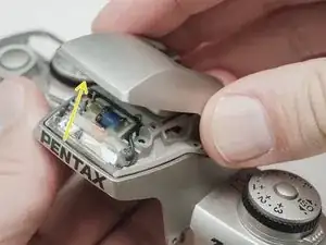
    • Close the flash and lift off the top cover.

  14. 6FAAoZXP1oGEAPDE
    6FAAoZXP1oGEAPDE
    wBGufY4vUxJkWQsb
    enfOmIDGNrGNgEHi
    • Remove one 3.4 mm #00 screw.

    • Remove the latch spring.

    • Remove the latch plate. The flash will try to pop up when it is removed.

  15. UuOjnPdjaJRnMYWd
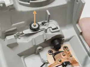
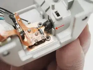
    • Release the spring arm from the post.

    • Remove the pop up spring.

  16. id1aFDUlRUBKqlyS
    id1aFDUlRUBKqlyS
    qB4QIX53usepwjLx
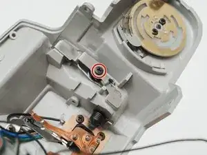
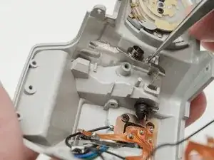
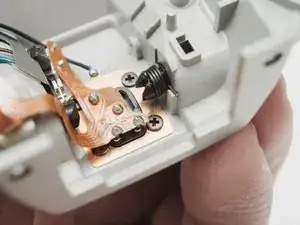
    • Remove one 3.3 mm #00 screw.

    • Hold the pivot in place while unscrewing.

  17. rpXvt42NwUBm2luS
    • When using the 3D printed part supplied on the device page, install a 4mm #00 screw in the end of the pivot to hold it together.

Abschluss

To reassemble your device, follow these instructions in reverse order.
Sam Gustafson

Mitglied seit: 02/09/22

1920 Reputation

0 Kommentare