Einleitung
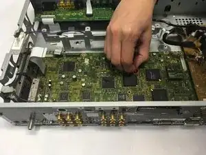
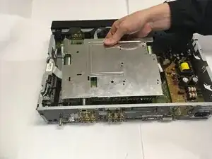
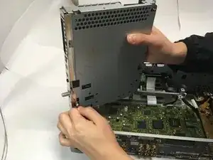
Replacing the motherboard of the Pioneer Elite Pro-R06U may be necessary if the receiver is dropped or takes water damage. This part is the trickiest to replace as it is located beneath all other components of the receiver.
Werkzeuge
-
-
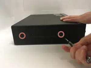
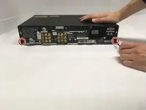
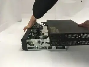
Grip the front panel in one hand and the back of the casing in the other. Pull the casing back, and slide it up and away from the inner box.
-
-
-
To replace the back cooling fan, grip the ribbon connector at slot M10 and remove by gently pulling upward.
-
-
-
Grip the frame of the cooling fan and slide away from the back wall until the tabs are no longer in the holes of the casing.
-
Lift the cooling fan out of the device.
-
-
-
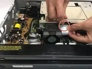
To remove the optical drive cooling fan, grip the ribbon connector at M11 and gently remove by pulling away for the slot.
-
-
-
Flip the latch on the ribbon connector upward to allow for cable removal.
-
Grip the ribbon cable and remove by gently pulling away from the unlatched connector.
-
-
-
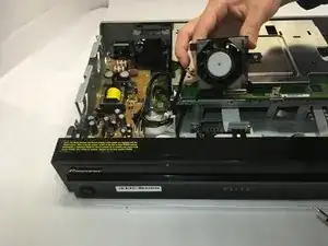
Grip the frame of the cooling fan and slide it toward the front panel, then lift out of the device.
-
-
-
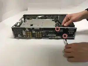
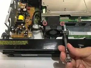
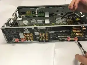
Remove four 1/4th inch Phillips screws on the back of the casing.
-
Unscrew and remove the nut from the threaded connector.
-
-
-
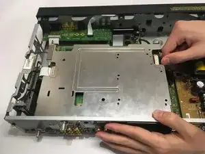
Pull the optical drive toward the interior of the device and then lift upwards, then pull to remove the cord on the bottom left corner before removing the drive completely.
-
-
-
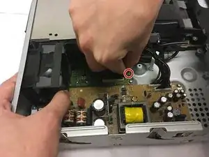
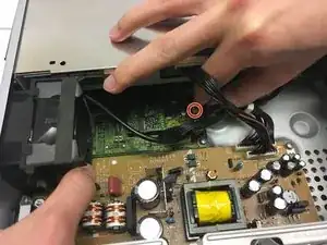
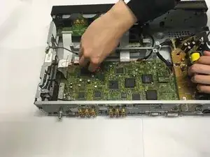
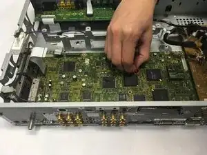
Unplug connectors at M1, M4, M7, M8, M9 by gently pulling upward.
-
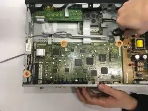
Remove all 3/8 inch Phillips screws connecting motherboard to casing.
-
-
-
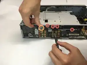
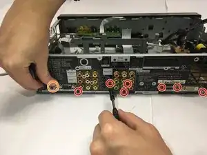
Remove the five 1/4 inch Phillips screws and two 1/8 inch Phillips screws on the back of the casing.
-
Unscrew and remove nut from threaded connector.
-
-
-
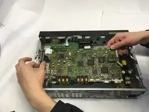
Pinch the securing tabs and lift the motherboard toward the interior of the device to remove it.
-
To reassemble your device, follow these instructions in reverse order.
