Einleitung
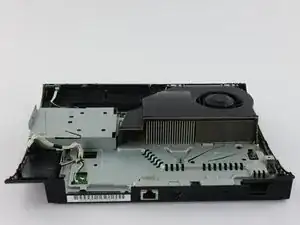
If your PlayStation 3 Super Slim's fan is making unreasonably loud noises or if your device keeps overheating, consider using this guide to replace it. Before following the steps to replace your fan, be sure that you have all the tools required to replace it, enough free time to take apart your device with care, and a clean and uncluttered working space. Be sure to be gentle with your device when following these steps to ensure that you replace your fan correctly.
Werkzeuge
Ersatzteile
-
-
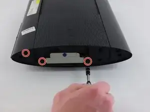
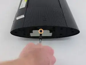
Remove all three black 9.8mm long screws with a T-8 security screwdriver.
-
Remove the blue 7.9mm long screw with a Phillips #1 screwdriver.
-
-
-
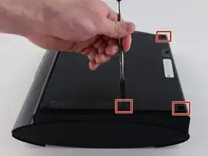
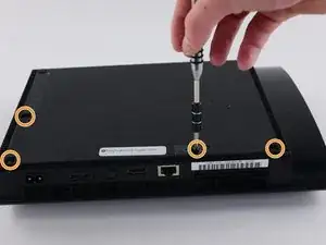
On the bottom of the device, pry out the three rubber feet covers with the metal spudger.
-
Remove the four black 36.3mm long screws underneath with a Phillips #1 screwdriver.
-
-
-
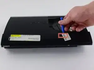
On the top of the device, unlatch the hook on the furthest right beneath the front panel, lift the panel slightly and apply pressure.
-
Unlatch the second right-side hook by sliding a plastic opening tool in the marked area.
-
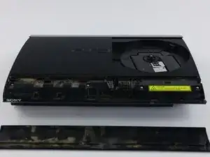
Slide the panel to the left to unlatch the rest of the hooks.
-
-
-
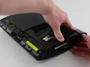
Remove the back panel by pressing down the tab on the right side of the device, and sliding the panel to the left.
-
-
-
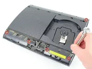
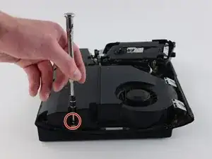
Remove the five silver 20.8mm long screws with a Phillips #1 screwdriver.
-
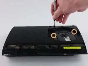
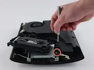
Remove the two black 9.9mm long screws in the disc reader with a T-8 security screwdriver.
-
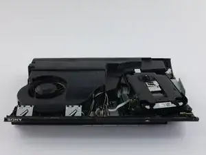
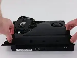
Remove the top black plastic shell.
-
-
-
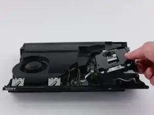
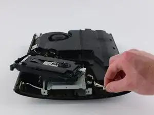
Move the optical drive to the side to reveal one of the silver 8.8mm long screws.
-
Remove the two silver 8.8mm long screws on either side with a Phillips #1 screwdriver.
-
-
-
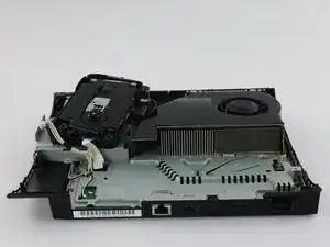
Remove the cable from the plug and remove the wires from the two plastic hooks.
-
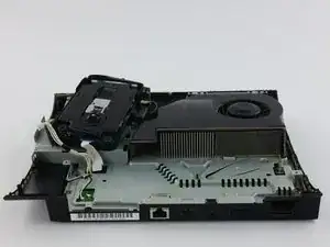
Remove the power supply unit.
-
-
-
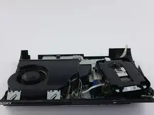
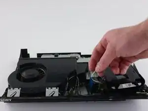
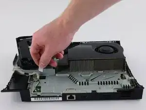
Remove the front white flex-ribbon cable by pulling upward from its base.
-
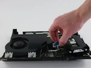
Remove the black and blue flex-ribbon cable behind it by pulling upward on the black tab, then pulling out the cable.
-
-
-
Rotate the device 180 degrees.
-
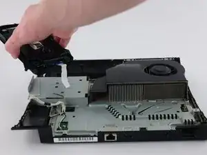
Remove the back white flex-ribbon cable by pulling upward from its base.
-
Remove the optical drive.
-
-
-
Locate the white flex ribbon cable that connects the power button to the motherboard. Pull this cable out from the motherboard end.
-
Remove the five black 8.3mm long screws with a Phillips #1 screwdriver.
-
Remove the two silver 12.8mm long screws with a Phillips #1 screwdriver.
-
Remove the device from the bottom shell casing.
-
-
-
Remove the two black 8.3mm long screws with a Phillips #1 screwdriver from the Wi-Fi antennas.
-
Lift the Wi-Fi antennas off their mount.
-
-
-
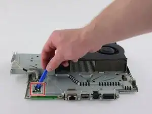
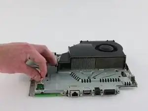
Use a plastic opening tool to remove the Wi-Fi wires from their sockets on the motherboard.
-
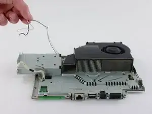
Remove the wires from the hooks around the motherboard and fan cover to completely remove the antennas.
-
-
-
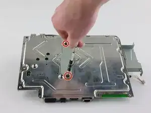
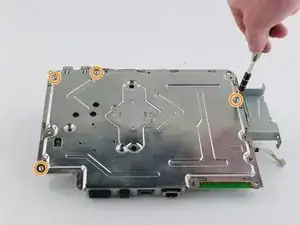
Remove the two black 14.5mm long screws with a Phillips #1 screwdriver from the center of the bottom metal casing.
-
Remove the four silver 8.7mm long screws with a Phillips #1 screwdriver around the edges of the bottom metal casing.
-
Remove the bottom metal casing.
-
-
-
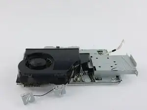
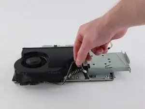
Remove the fan wire from its plug on the top metal casing.
-
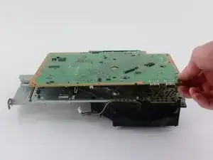
Remove the motherboard from the top metal casing. Lift from the side with the two USB plugs to avoid damaging the four back ports.
-
-
-
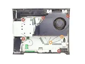
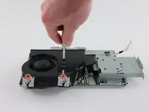
On the bottom of the top metal casing, remove the three black 8.0mm long screws with a Phillips #1 screwdriver.
-
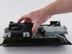
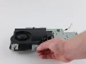
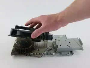
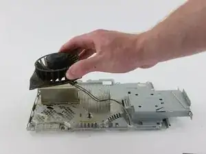
Remove the fan from the plastic cover.
-
Install the replacement fan. To reassemble your device, follow these instructions in reverse order.
Ein Kommentar
Thanks for this fan tutorial I have not been able to find any on YouTube about taking apart the fan for cleaning the heat sync's and fan blades it self. So thank you so very much.
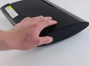
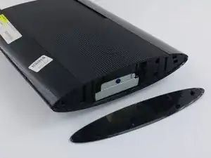
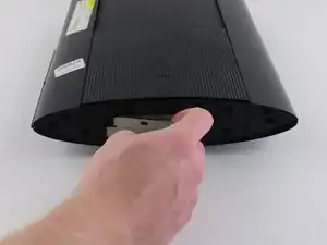
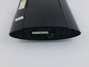
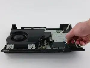



Just wanted to add: the HDD bay cover isn't on the right all the time, it varies with each unit. The side without the rubber PS logo is the bay cover.
Yash -