Einleitung

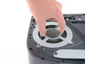
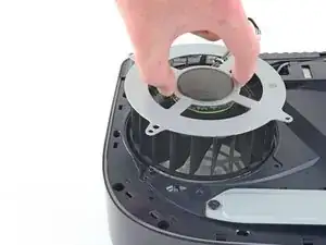
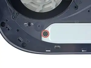
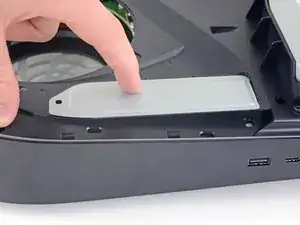
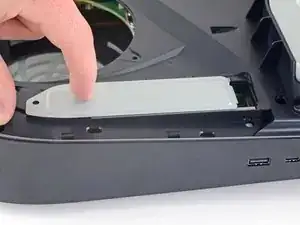
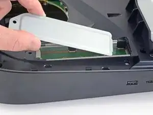
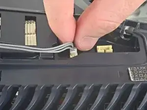
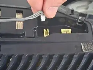
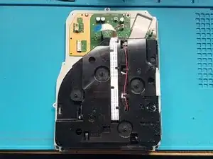
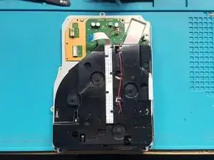
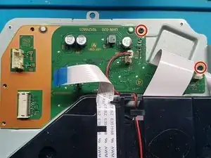
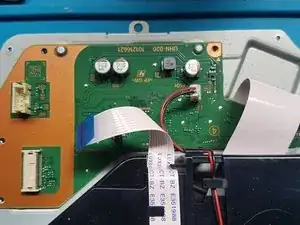
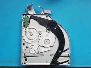
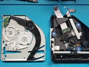
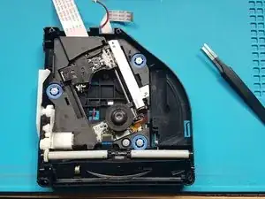
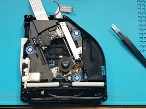
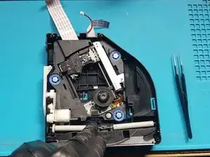
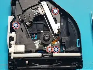
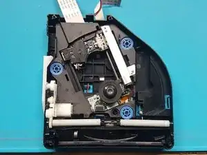
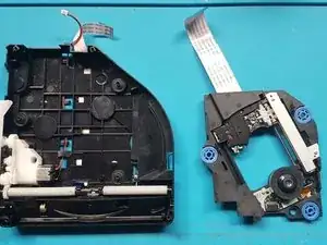
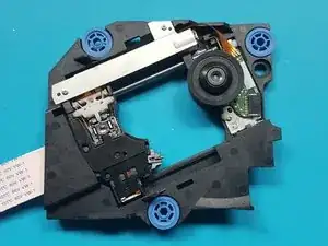
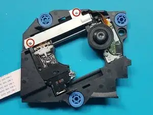
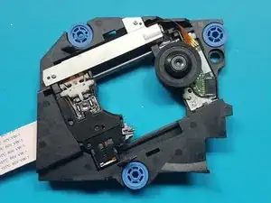
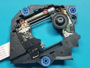
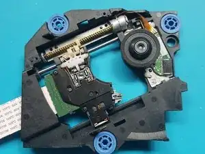
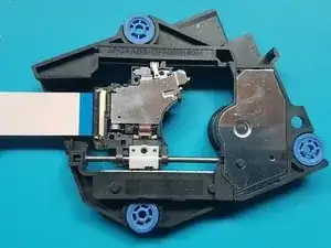
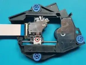
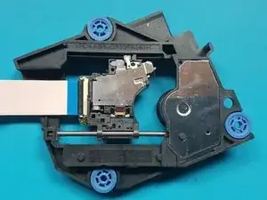
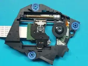
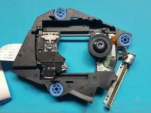
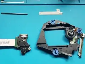
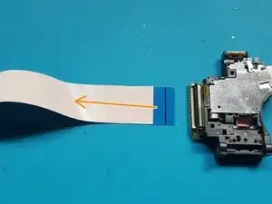
Follow this guide to remove and replace the laser on a PlayStation 5.

Before you begin, completely power down and unplug all cables from your console. Remember to follow general electrostatic discharge (ESD) safety procedures while repairing the console.

  1. tccurcEsCV2Jem41
    • If your PlayStation 5 is in its vertical orientation, flip it upside down so the stand is facing up.

    • If your PlayStation 5 is in its horizontal orientation, skip to Step 6.

    • Work on a flat surface to prevent your PlayStation from falling over.

    • Use a coin or a flathead screwdriver to remove the 26.5 mm-long stand screw.

  2. GTbQeM3BQhiOdLSH
    GTbQeM3BQhiOdLSH
    pPvQrFR3QxJcona3
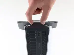
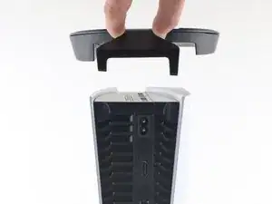
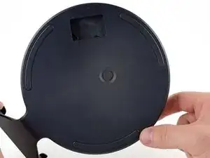
    • Lift straight up to remove the stand.

  3. 5ON3Z62eTgwwefAh
    5ON3Z62eTgwwefAh
    N2e3QE2E1XNbJaTK
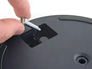
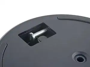
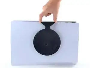
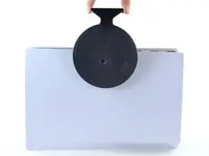
    • Insert the screw into the cubby on the bottom of the stand.

  4. c5wyLQEXQVvdxnMV
    c5wyLQEXQVvdxnMV
    TFfMjCrwb3lo5jM1
    vPxMbWYwZN4wgHAa
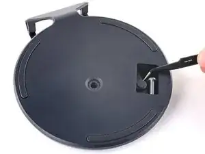
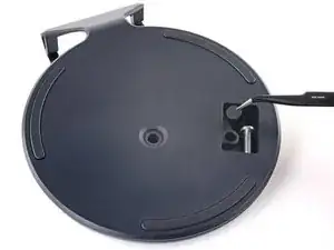
    • Use a pair of tweezers or your fingernail to remove the cap from the cubby.

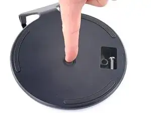
    • Use your finger to press the cap into the screw hole.

  5. xXLuv4RjbvQuoOV2
    xXLuv4RjbvQuoOV2
    fgJrA5NsMKQaFaJq
    UTxfr1FuAInSlfD5
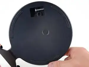
    • Twist the stand counterclockwise to close the cubby.

  6. CNkg1VhN2eJYqVaj
    CNkg1VhN2eJYqVaj
    hgKZF2u42g1v2Zfx
    • If your PlayStation 5 is in its horizontal orientation, rest it on its face with the charging port facing up.

    • Lift the stand straight up to remove it.

    Do you guys sell the stand

    Corey Lewis -

  7. LcrhX64CyClbCTyU
    LcrhX64CyClbCTyU
    KIs1TBMRtWCtHVLI
    UiHOlog2OVSISG6K
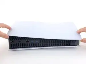
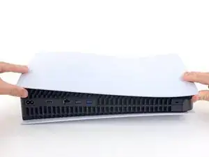
    • Flip the device over so that the USB and ethernet ports are on the left side from your perspective.

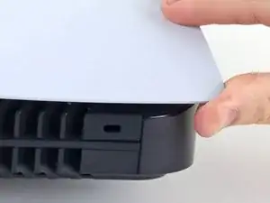
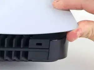
    • Lift up the corner of the faceplate to unclip it from the case.

  8. 6TMacJpc5EMtNJNO
    6TMacJpc5EMtNJNO
    rVlWuNJU3Lp5KZuV
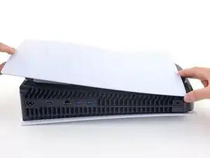
    • While lifting up the corner, slide the faceplate towards the bottom of the device.

    • Remove the right faceplate.

  9. YgZyMg4eEWlcSKGq
    YgZyMg4eEWlcSKGq
    JmIJfTECQLy2himU
    aSZgkXtNBqA26bO2
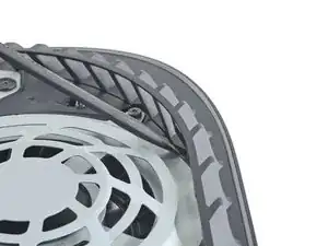
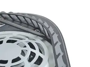
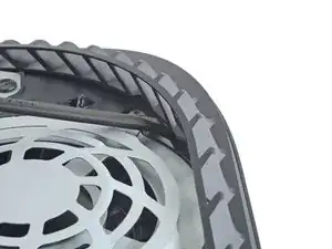
    • Insert the flat end of a spudger underneath the grille and into the gap above the fan.

    • Lift up with the spudger to pry the grille away from the case.

  10. EhpjIQpGo2JfVQio
    EhpjIQpGo2JfVQio
    EMbHifxKWRi3DQZx
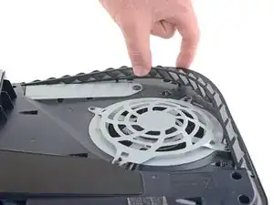
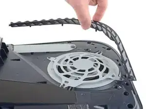
    • Lift the grille away from the case to remove it.

  11. tKEPaKx5Re4OyrMO
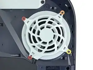
    • Use a T8 Torx driver to remove the four screws securing the fan shroud to the case:

    • Two 23.3 mm-long screws

    • One 11.4 mm-long screw

    • One 31 mm-long screw

    • Throughout this repair, keep track of each screw and make sure it goes back exactly where it came from to avoid damaging your console.

    My ps5 seems to have tiny black caps over each screw. My spudger can’t get them off I see no other way to move forward besides breaking the shroud

    Anthony Pouliot -

    wrong side, take the cover off the other side

    Alan Sears -

    The 31 mm-long screw just wont budge! do I turn that one counter-clockwise or clockwise? someone please help!

    Chris Love -

    counter clockwise to remove

    Alan Sears -

    I damaged the 23.3mm on the bottom right next to fan connector. Is there any replacements? Can't seem to find any 23.3mm t8 screw anywhere online

    forsage.rh -

    I used a t8 for all of them and had no problem removing, except for that bottom right screw

    forsage.rh -

    Is there any replacement screws you can buy for the fan? I slightly damage 23.3mm screw.

    Kevin Sarmiento -

    My PS5 has TX8 (security Torx bit) screws on my fan shroud and all the case screws. A normal Torx driver won’t work you need the one with the hole in the middle of the bit driver.

    Daniel Sutczak -

    Why does my ps5 have 3 different screws? 2 are the same then 2 other ones? Why?

    GoodContentKing -

  12. wrISkxRdTVweXuug
    wrISkxRdTVweXuug
    McNLVJ2SXRtW66DI
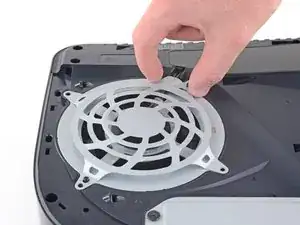
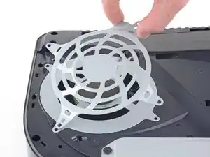
    • Lift the fan shroud straight up to remove it.

    wo bekomme ich die original Torx M8 für die Ps5?

    Elli Pirelly -

  13. Kpw4iBoZ4CymHtJ3
    Kpw4iBoZ4CymHtJ3
    YDc55ikpOSTXwSDj
    3LXMZkBflYrrll6D
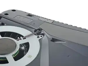
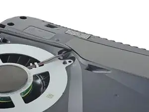
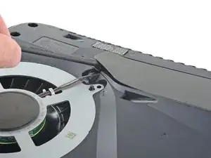
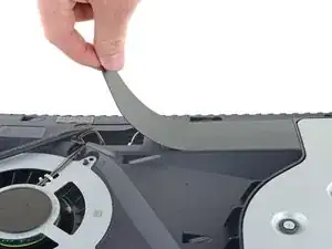
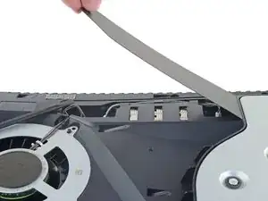
    • Insert the flat end of a spudger beneath the black wire cover and into the gap above the fan wires.

    • Pry only on the wire cover, not on the fan wires themselves.

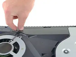
    • Use the spudger to peel up the wire cover until you can grip it with your fingers.

  14. crnAyDsoDlXYBlam
    crnAyDsoDlXYBlam
    hVbaRGoQ6nifrPfx
    VVBhYFJL6DosqWJD
    • Use your fingers to peel off the wire cover.

  15. HD5KLVUXbJfFfcWL
    HD5KLVUXbJfFfcWL
    fByEpECKLDsYjZLR
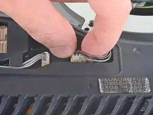
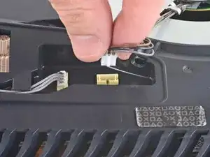
    • Use your fingers to grip the edges of the fan cable connector, and pull up to disconnect it from the motherboard.

    • Always pull cables by their connectors and not the wires themselves.

  16. DQ42DYLfTkBAHkfk
    DQ42DYLfTkBAHkfk
    EVoYkCrZkrMe1mFT
    IACOgufSsbI3IyZN
    • Lift the fan up and out of the case to remove it.

  17. rtvMeF2ZTcjegknS
    • Use a Phillips screwdriver to remove the 17 mm-long SSD cover screw.

  18. IvEneJ4yyDIKhm4A
    IvEneJ4yyDIKhm4A
    qv6dWJYA6hIOHypN
    OCSrcBOBSLHhcLMY
    • Use your finger to slide the SSD cover towards the top of the device to unclip it from the case.

    • Remove the SSD cover.

    It is unnecessary to remove the SSD screw and cover for power supply replacement.

    Daniel Sutczak -

  19. mmQGHK3TUG5nRc54
    mmQGHK3TUG5nRc54
    qKlQhQJDjZCXiuXc
    • Use your fingers to grip the edges of the optical drive cable connector, and pull up to disconnect it from the motherboard.

    • Always pull cables by their connectors and not the wires themselves.

  20. Be3FnVnHnCDj4RpX
    Be3FnVnHnCDj4RpX
    jEUiixElyEPN6tbL
    • Use your fingers to grip the edges of the optical drive cable connector, and pull up to disconnect it from the optical drive.

  21. lJ2iCsYMpJSJXgEj
    lJ2iCsYMpJSJXgEj
    JQCyDUucB6irbaZx
    kMPDPSHS6UUbene4
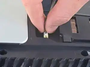
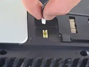
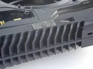
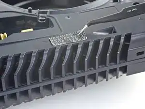
    • Use a pair of tweezers to remove the tamper-evident sticker covering the remaining case screw.

    • If your PlayStation 5 hasn't been opened before, this sticker will be completely black. The pattern will appear after you remove it.

    • Technically, these are tamper-evident stickers—but don't worry—Sony can't legally void your warranty, as long as you don't damage anything. Have fun!

  22. qssP1bCSpXhKBEBk
    • Use a T8 Torx driver to remove the eleven screws securing the case:

    • Six 18.6 mm-long screws

    • Two 23.3 mm-long screws

    • Two 43.2 mm-long screws

    • One 7.3 mm-long screw

  23. 5IXVsU3vwHU2inv4
    5IXVsU3vwHU2inv4
    MquyR2EC5JoWp5My
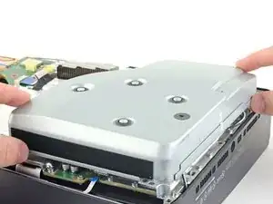
    • Lift the case straight up to remove it.

  24. uSYNtWqOREfmSVpF
    uSYNtWqOREfmSVpF
    rBu6EOCV3gB1S56y
    3DJniqQUSXHh6Shn
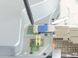
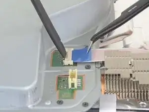
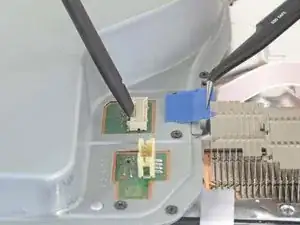
    • Use the flat end of a spudger to press down on the optical drive connector's metal locking tab.

    • With the metal tab depressed, use a pair of tweezers to pull the blue pull tab directly away from the connector to disconnect the cable from the optical drive.

    • Pull only on the pull tab, not the cable itself.

  25. egW5A2jhSYg1uWxL
    egW5A2jhSYg1uWxL
    DrmnGYEwnUnasrQl
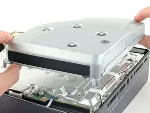
    • Lift the optical drive away from the device to remove it.

  26. FNXPKCOJ4Nv6UCn3
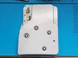
    • silver screws: 4x M1.6 X 3.7mm, with 6.5mm head.

    • black screws: 9x M1.6 x 3.8mm.

    • Remove screws with Phillips #1 screwdriver.

  27. Jkb6s56CBgBC4bR2
    Jkb6s56CBgBC4bR2
    OAeM2TOZsZPtHbQN
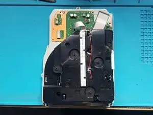
    • Lift off the top cover.

  28. 3oLrqtcAGBIXQYup
    3oLrqtcAGBIXQYup
    xItpWbnTdRJMrC4D
    NGR5kK1utrdIjqNB
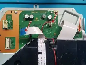
    • Gently pull the medium and narrow FFC flexes and the 2-wire lead from their sockets. Suitable tweezers (bent with points or straight blunt end) can be used to aid removal.

  29. SI2QlKqSODxQJwkX
    SI2QlKqSODxQJwkX
    gNMwUDIhhPvY6gJI
    • Remove screws with Phillips #1 screwdriver.

    • black screws: 2x M1.6 x 3.8mm

  30. NBZYifHKZGUbXHHv
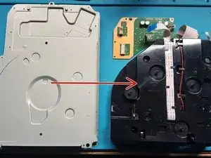
    • Lift off the PCB and attached assembly from the metal plate.

  31. UwmGdKfkX1hJr5eh
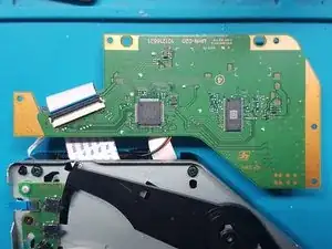
    • Turn over the PCB and attached assembly.

  32. VEpLL2MOmgOB4a3Z
    VEpLL2MOmgOB4a3Z
    ZYqvX1Q3yuA22vVk
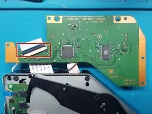
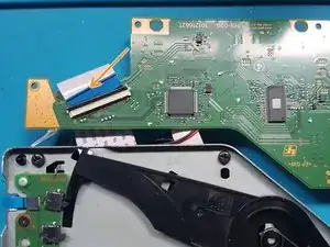
    • Unlatch the wide FFC socket.

    • Gently remove the wide FFC cable from the socket and set aside the PCB.

  33. fVFaQy5J2GJS1f1R
    • Flip over the assembly.

  34. wnwRyajMIcg1nKdv
    wnwRyajMIcg1nKdv
    ZNTZCjHOTl6C6rMt
    • Use a Phillips #1 screwdriver to remove the screws.

    • black screws: 4x M1.6 x 3.8mm.

  35. txwGJLNRE6EKHP6u
    txwGJLNRE6EKHP6u
    RLZycHUubXEWQMtV
    NHOuGwNSTGk6tOsO
    • Remove the mechanism plate and set aside.

  36. fJKglNDKZ6EmcEEw
    fJKglNDKZ6EmcEEw
    WIeYJtSCeHJ1qbZ2
    FiQpCHt6NHHUZnCE
    • Push down on the roller mech and remove the FFC cable from laser deck (near roller mech).

    • Blunt end straight tweezers can be used to aide removal of the FFC flex. To remove the flex from the socket, pull the flex towards the rollers.

  37. ETrMVYL5cuOdXspM
    ETrMVYL5cuOdXspM
    pkQsIXnxnwUBCJd4
    • Remove the screws using a Phillips #1 screw driver.

    • silver screws: 4x M1.6 X 3.7mm 6.5mm head

  38. AMpVyumarbyLOcEM
    AMpVyumarbyLOcEM
    WuQnHnJbe5m5xuPB
    • Remove the laser deck.

  39. TjdyEWqTAR5DeRTO
    TjdyEWqTAR5DeRTO
    TtNKOjCgCNMudeOj
    • Remove the screws from metal plate over laser motor.

    • Use a Phillips PH0 screwdriver to remove the screws.

    • silver screws: 2x M1.7 X 3.8mm

  40. u23RHcjkbNjGqNVV
    u23RHcjkbNjGqNVV
    f2HcTgeInIAf1I4P
    • Remove the metal plate covering the laser motor.

  41. A2ILWDfDBDQMWIYI
    A2ILWDfDBDQMWIYI
    Nh1gcACCRrNDwB1e
    • Remove the screws holding the laser motor to the drive deck.

    • Use a Phillips PH0 screwdriver to remove the screws.

    • silver screws: 2x M1.7 X 3.8mm

  42. 4PyWrVIAH2mf3mUC
    4PyWrVIAH2mf3mUC
    vCY5UTVU55P6yMZ2
    ZIhLy1v6XFhoXZVi
    • flip over and remove a single black screw from white plastic bracket.

    • Note: laser motor will be loose, so be careful when you flip over the deck for the next step.

    • Remove the screw with a Phillips PH0 screwdriver.

    • black screw: 1x M1.4 x 3.9mm

    • Remove the white bracket and set aside.

  43. yCLTfY1wZKG33wso
    yCLTfY1wZKG33wso
    QxfgnBl3LGMRZDD6
    • Flip over the laser deck and move the laser motor to the side

  44. BQnUVYluH2DAcRQv
    BQnUVYluH2DAcRQv
    RE2qKCdWGSHsNyvO
    uqjJGjDGXJEtXBFm
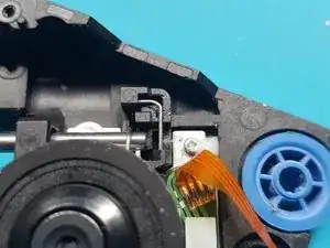
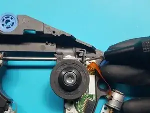
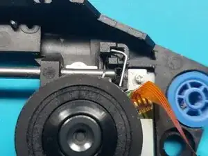
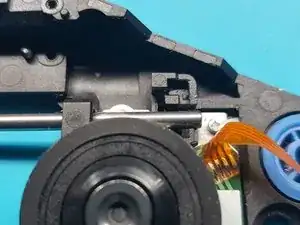
    • remove the clip that stops the rod from being removed.

    • a) Use a 1.5mm slotted screwdriver to push the lower end of the clip to the left, to unhook it from the retaining hook.

    • b) The clip should pop up.

    • c) lift out the clip.

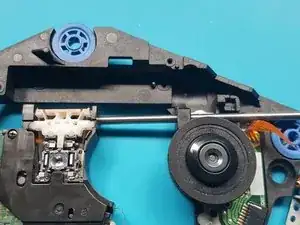
  45. QrgCC113kjCmJadY
    QrgCC113kjCmJadY
    dSNqZv1wJuwGeFGF
    xbpIxuiYutYWDwAC
    • slide out the rod from the laser module.

  46. Ob6iMJIal2jxJTtc
    Ob6iMJIal2jxJTtc
    QNTVvBVuxdPXAgUC
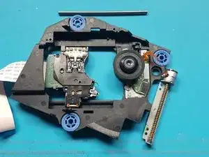
    • Remove the laser module

  47. GbVAF4bMUtgFDrJA
    GbVAF4bMUtgFDrJA
    mSDoqwXm3UVHMGhu
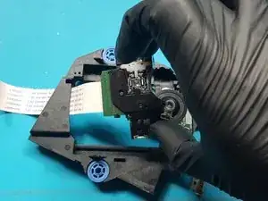
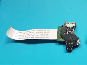
    • Flip over the laser module.

  48. 3IE3WjXtlGH14gbY
    3IE3WjXtlGH14gbY
    PMy5dHl3a2CVkvjE
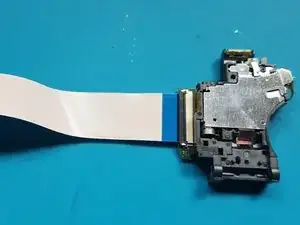
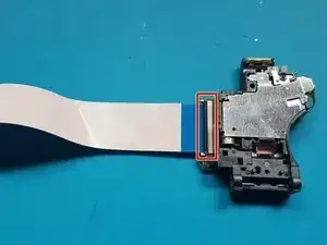
    • unlatch the FFC connector.

    • Remove the FFC flex from the laser.

Abschluss

To reassemble your device, follow these instructions in reverse order.

Take your e-waste to an R2 or e-Stewards certified recycler.
Repair didn’t go as planned? Try some basic troubleshooting, or ask our PlayStation 5 Answers community for help.
David Fear

Mitglied seit: 10/06/17

377 Reputation

0 Kommentare