Einleitung
Use this guide to replace a cracked or cosmetically damaged front display bezel.
-
-
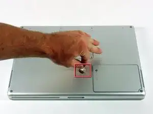
Use a coin to turn the battery locking screw 90 degrees clockwise.
-
Lift the battery out of the computer.
-
-
-
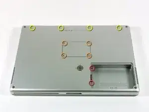
Remove the following 10 screws:
-
Two 3 mm Phillips in the battery compartment, on either side of the battery contacts.
-
Four 3 mm Phillips around the memory compartment.
-
Four 16 mm Phillips along the hinge.
-
-
-
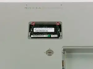
Remove the memory compartment cover.
-
Remove the two 12 mm Phillips screws on the Aluminum bracket at the top of the memory compartment.
-
-
-
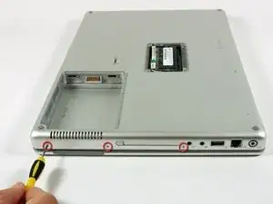
Rotate the computer 90 degrees clockwise so the power receptacle faces you.
-
Remove the three 3 mm Phillips screws along the edge of the lower case.
-
-
-
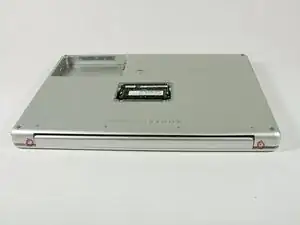
Turn the computer 90 degrees clockwise so the hinge faces you.
-
Remove the lower 5 mm Phillips screw on each side of the hinge (two total).
-
-
-
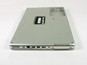
Rotate the computer 90 degrees clockwise so the ports face you.
-
Remove the three 3 mm Phillips screws along the edge of the lower case.
-
When replacing these screws, you must install them in the correct order. Begin by installing the screw closest to the display hinge, then work your way toward the front of the computer. Also, be careful not to put the screws in the two holes on either side of the video out port.
-
-
-
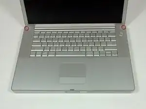
Turn the computer over and open the display.
-
Remove the two 4.2 mm long, 1.5 mm hex screws at the top corners of the upper case (two total).
-
-
-
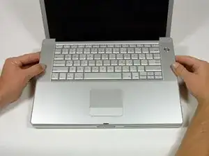
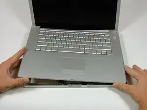
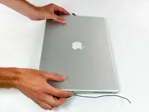
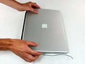
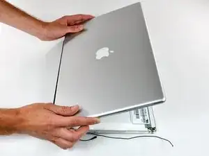
Grasp the back corners of the upper case and pull up.
-
Lift the back of the case up and work your fingers along the sides, freeing the case as you go. Once you have freed the sides, you may need to rock the case up and down to free the front of the upper case.
-
-
-
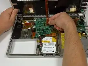
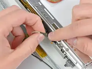
Remove the amber tape securing the trackpad ribbon to the logic board.
-
Disconnect the trackpad ribbon from the logic board by pulling up on the connector.
-
Remove the upper case from the computer.
-
-
-
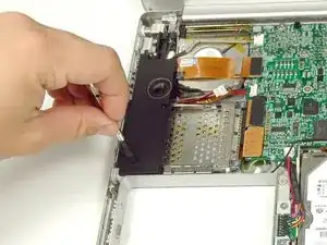
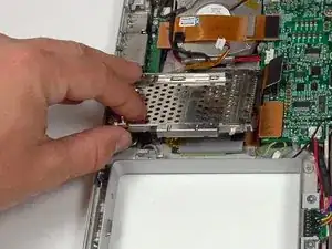
Remove the two 3 mm Phillips screws securing the left ambient light sensor. One is silver and one is black, or both black.
-
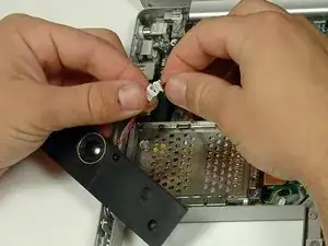
Disconnect the cable from the Logic board and remove the left ambient light sensor from your computer.
-
-
-
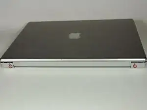
Close the display and turn the hinge side of the computer to face you.
-
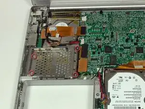
Remove the remaining 5.2 mm Phillips screws on either side of the hinge (two screws total).
-
-
-
Remove the upper two full thread 10 mm T8 Torx screws from each side of the display, then the two lower shanked 13 mm screws (four screws total).
-
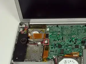
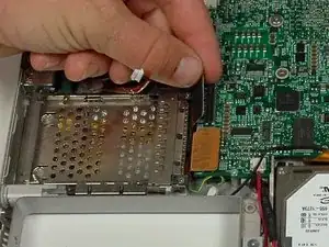
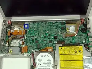
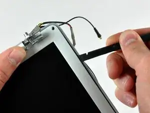
Disconnect the two antenna cables from the airport/bluetooth card (shown in yellow circles), as well as the display cable (wide connector right hand upper corner) and the cable on top left corner of the logic board (shown in blue square).
-
-
-
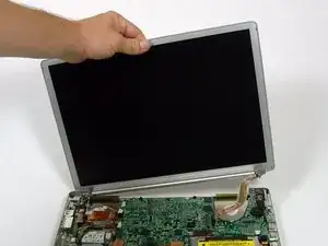
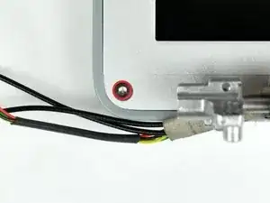
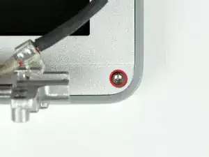
Remove the two 6mm long, 1.5 mm hex screws near the lower left and right corners of the display.
-
-
-
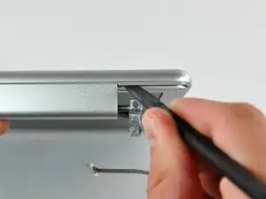
Insert the flat end of a spudger between the front display bezel and the plastic rim attached to the rear bezel near the lower left corner of the display.
-
-
-
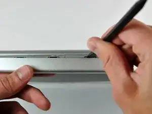
With your spudger still inserted under the front display bezel, run it around the lower left corner of the display.
-
Rotate the spudger away from yourself to pry the rear display bezel off the aluminum tabs on the front display bezel.
-
Work your way down the side of the display until the rear display bezel has been separated from the front display bezel.
-
-
-
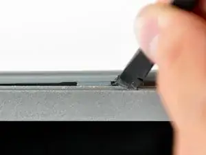
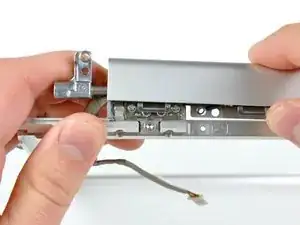
Insert the flat end of a spudger between the rear display bezel and the clutch cover.
-
Twist the spudger to unclip the rear bezel from the clutch cover.
-
-
-
Repeat the previous steps to separate the right side of the rear display bezel from the display.
-
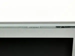
Use your spudger to pry the plastic retaining clips on the rear display bezel over the raised aluminum tabs on the front display bezel.
-
At this point, the clips on the left and right edges of the rear display bezel should be free from the raised aluminum tabs on the front display bezel. If they are not, use a spudger to pry them past the front display bezel.
-
-
-
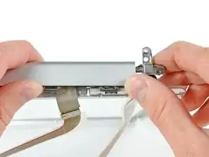
Slightly lift the lower edge of the rear display bezel and push it toward the top edge of the display, releasing the clips along the top edge of the rear display bezel.
-
Rotate the rear display bezel toward yourself and lay it flat on the table.
-
-
-
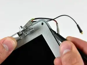
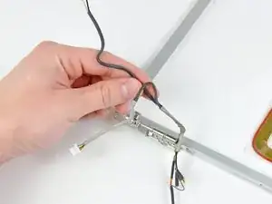
Disconnect both antenna cables from the rear display bezel.
-
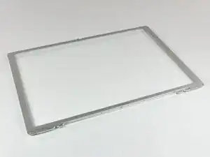
Remove the rear display bezel and set it aside.
-
-
-
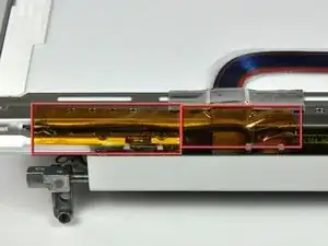
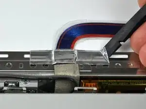
Use the flat end of a spudger to remove the piece of foil tape securing the display data cable to the LCD frame.
-
-
-
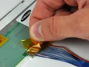
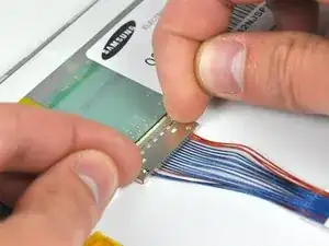
Pull the display data cable connector away from its socket to disconnect it from the LCD.
-
-
-
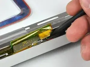
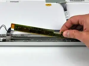
Use a spudger to raise the end of the inverter out from the clutch cover.
-
Lift the inverter enough to access both cable connectors.
-
-
-
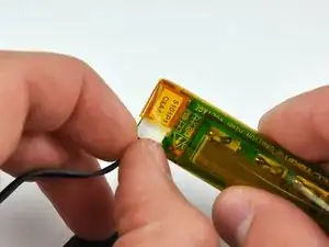
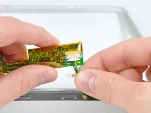
Disconnect the inverter cable by pulling its connector away from the socket on the inverter board.
-
-
-
Flip your display over so the front bezel is facing up.
-
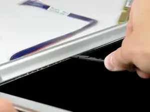
Lift the front bezel off the LCD enough to insert the flat end of a spudger between the metal LCD frame and the front display bezel.
-
Run your spudger along the lower edge of the front display bezel to separate the adhesive from the LCD frame.
-
-
-
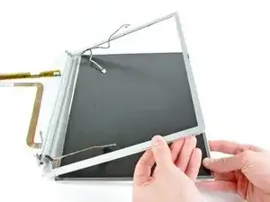
Pull the LCD toward the top edge of the front display bezel, minding any cables that may get caught.
-
-
-
If necessary, lift the inverter out from the clutch cover.
-
Disconnect the inverter cable by pulling its connector away from the socket on the inverter board.
-
-
-
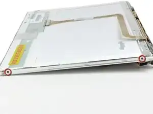
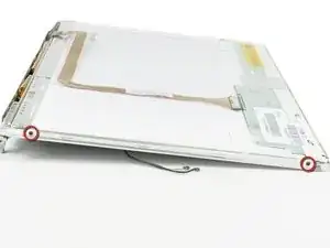
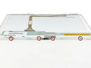
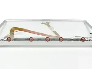
Remove the five Phillips screws securing the LCD retaining bracket to the front display bezel.
-
Lift the LCD retaining bracket off the front display bezel.
-
-
-
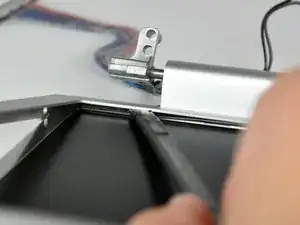
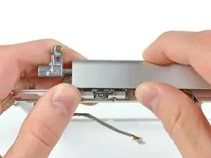
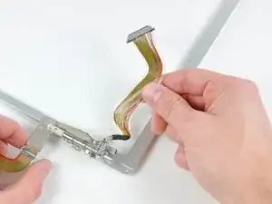
Use your thumbs to push the clutch cover away from the clutch hinges.
-
While pressing with your thumbs, rotate the clutch cover toward yourself about its long edge to pop it off the clutch hinge.
-
Repeat this process for the other side of the clutch cover. Once the clutch cover is completely free from the clutch hinges, lift it off the front display bezel.
-
-
-
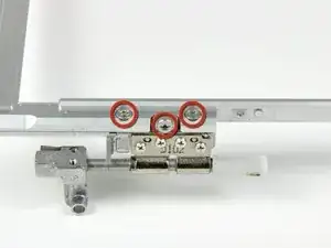
Remove the three T8 Torx screws securing the right clutch hinge to the front display bezel.
-
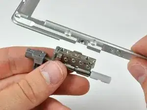
Remove the right clutch hinge and set it aside.
-
-
-
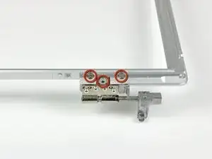
Remove the three T8 Torx screws securing the left clutch hinge to the front bezel.
-
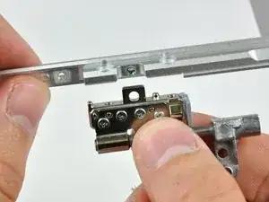
Remove the left clutch hinge and set it aside.
-

To reassemble your device, follow these instructions in reverse order.