Einleitung
Use this guide to replace just the LCD rather than the entire display assembly.
Ersatzteile
-
-
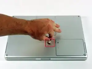
Use a coin to turn the battery locking screw 90 degrees clockwise.
-
Lift the battery out of the computer.
-
-
-
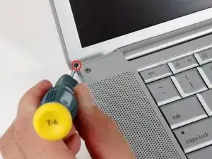
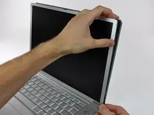
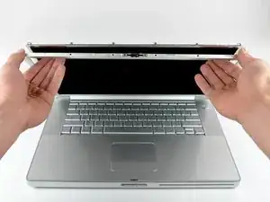
Open the computer with the display facing you and rotate the display back as far as possible.
-
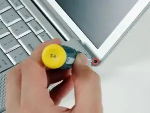
Remove the T6 Torx screw from the bottom left corner of the display assembly. The computer casing will not allow the screwdriver to be inserted directly into the screw, so be careful not to strip the screw.
-
-
-
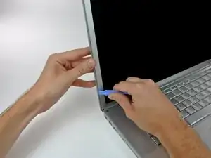
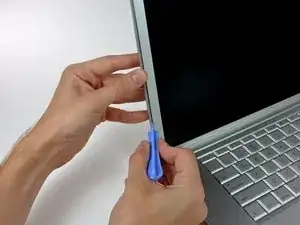
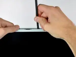
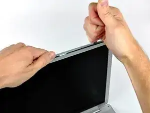
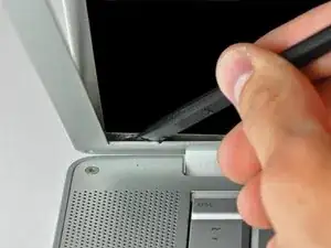
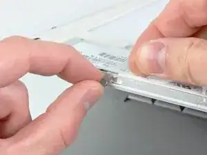
Insert a plastic opening tool between the left edge of the front display bezel and the plastic strip attached to the rear bezel, with the edge of the tool angled toward the LCD.
-
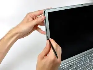
Rotate the tool away from the LCD to pop the rear bezel off the tabs on the front display bezel.
-
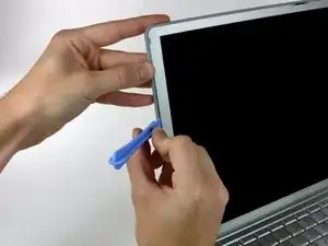
Work along the left edge of the display until the rear bezel is evenly separated from the front bezel.
-
-
-
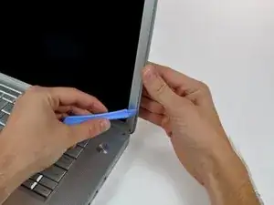
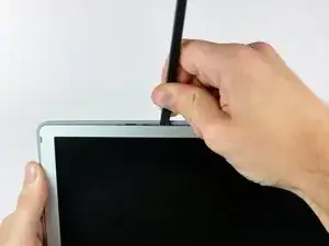
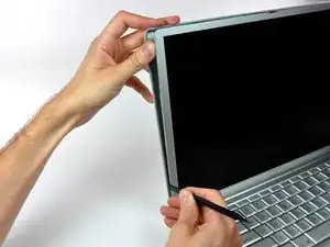
Insert a plastic opening tool between the right edge of the front display bezel and the plastic strip attached to the rear bezel, with the edge of the tool angled toward the LCD.
-
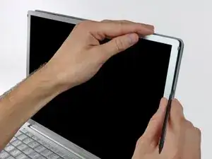
Rotate the tool away from the LCD to pop the rear bezel off the tabs on the front display bezel.
-
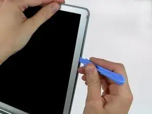
Work along the right edge of the display until the rear bezel is evenly separated from the front bezel.
-
-
-
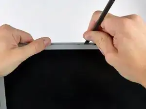
Insert a spudger just to the left of the hinge opening on the top edge of the display between the front display bezel and the plastic strip attached to the rear bezel.
-
Pry the rear bezel away from the front bezel along the top left half of the display.
-
-
-
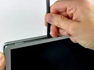
Insert a spudger just to the right of the hinge opening on the top edge of the display between the front display bezel and the plastic strip attached to the rear bezel.
-
Pry the rear bezel away from the front bezel along the top right half of the display.
-
-
-
Now that the top edge is released, use a spudger to completely release the clips along the left edge of the display.
-
-
-
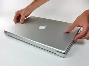
Close the display.
-
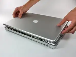
Rotate the top edge of the rear display bezel slightly away from the rest of the display, and then lift the lower edge of the rear bezel away from the clutch cover.
-
-
-
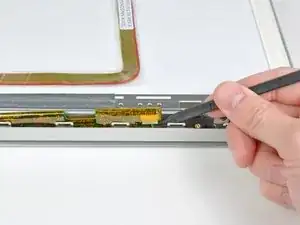
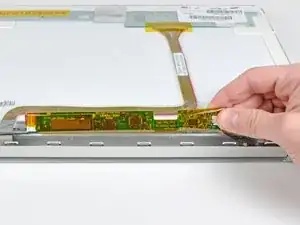
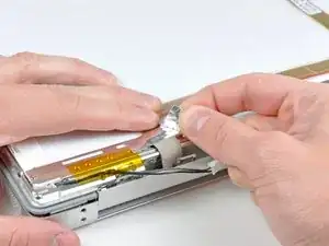
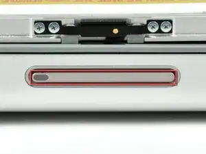
Using the tip of a spudger, raise the inverter out from the clutch cover.
-
Lift the inverter enough to reveal both cable connectors.
-
-
-
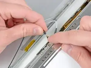
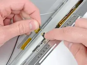
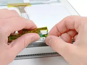
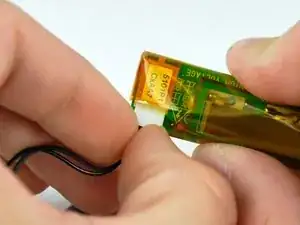
Disconnect both inverter cables by pulling their connectors away from the sockets on the inverter board.
-
Remove the inverter from the display.
-
-
-
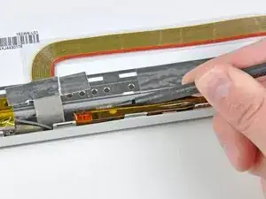
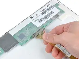
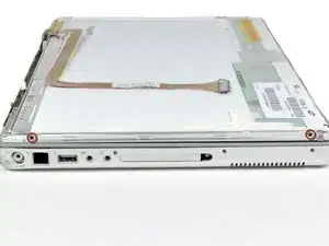
Pull the display data cable connector away from its socket to disconnect it from the LCD.
-
-
-
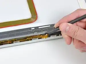
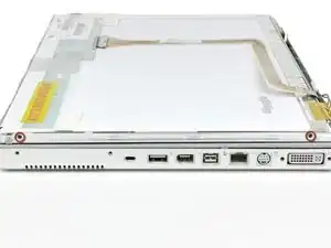
Lift the LCD off the front bezel enough to insert the flat end of a spudger between the metal LCD frame and the front display bezel.
-
Run your spudger along the lower edge of the front display bezel to separate the adhesive from the LCD frame.
-
-
-
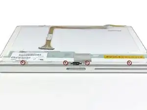
Remove the small magnet near the top left corner of the display, making sure to mark its orientation before removal.
-
-
-
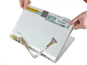
Pull the LCD toward the top edge of the front display bezel, minding any cables that may get caught.
-
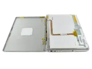

To reassemble your device, follow these instructions in reverse order.