Einleitung
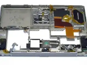
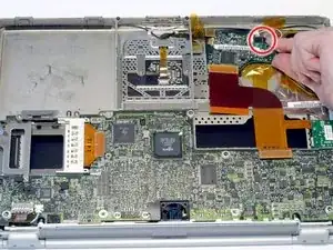
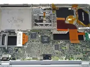
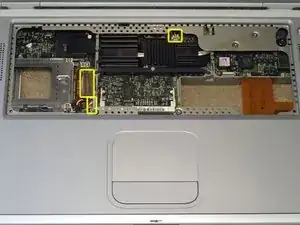
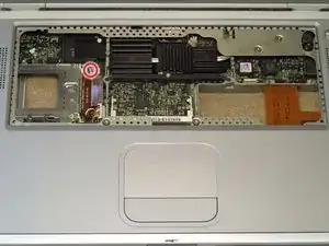
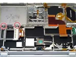
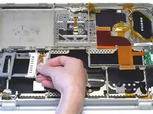
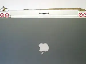
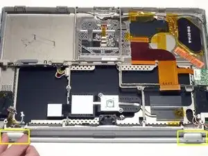
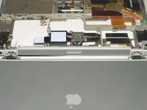
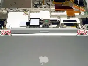
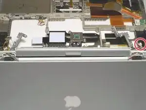
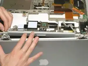
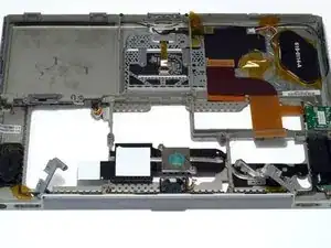
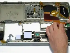
Changing the top case will also give you a new trackpad, but requires removing everything from the computer.
Werkzeuge
Ersatzteile
-
-
Remove the battery.
-
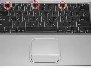
Turn the keyboard locking screw so that it is parallel to the space bar.
-
Pull the keyboard release tabs toward you and lift up on the keyboard until it pops free.
-
-
-
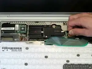
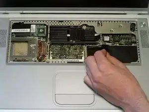
Rest the keyboard face down on the trackpad area.
-
Disconnect the keyboard connector from the logic board.
-
-
-
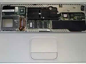
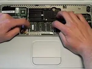
Release the tabs on each side of the RAM chip at the same time. These tabs lock the chip in place and releasing them will cause the chip to "pop" up.
-
Pull the RAM chip out.
-
Repeat this process if a second RAM chip is installed.
-
-
-
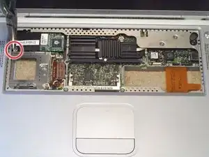
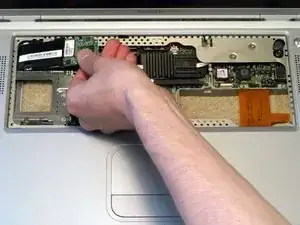
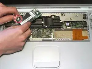
Firmly grasp the plastic tab attached to the Airport card and pull up and to the left.
-
Disconnect the antenna cable from the left side of the Airport card.
-
-
-
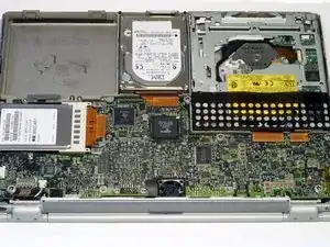
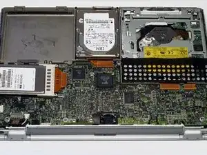
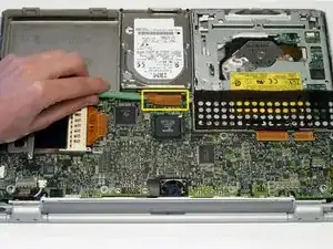
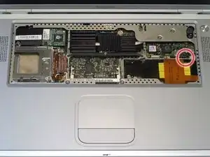
Disconnect the hard drive ribbon from the logic board using a spudger or the tip of your finger.
-
-
-
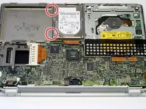
To free the hard drive, remove the two T8 Torx screws from the right wall of the battery housing.
-
-
-
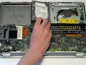
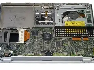
Remove the hard drive by gently grasping the orange ribbon cable and lifting the left edge up and out of the computer.
-
-
-
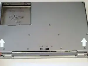
Before continuing, place a soft cloth on your work surface to rest the computer on. Turn the G4 over, making sure the DVD drive doesn't fall out.
-
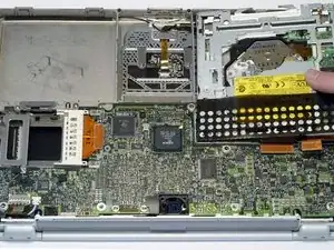
Carefully peel the adhesive strip away from the DVD drive. The plastic dust shield covering the DVD drive is easily damaged. Try to start at the four corners and work toward the center.
-
-
-
Bend the silver metal EMI clip so that it is vertical. This part may fall out after removing the DVD drive.
-
-
-
Turn the G4 over.
-
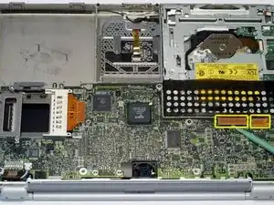
Disconnect both orange ribbon cables from the logic board using a spudger or the tip of your finger.
-
-
-
Turn the G4 over.
-
Using a 5 mm nut driver or needle-nose pliers, remove the hex nut from the modem.
-
-
-
Turn the G4 over.
-
Peel the orange tape away from the three connectors on the PMU board. Leave this tape in place so you can reuse it when reassembling the G4.
-
Disconnect the two orange cables and one multicolored cable from the PMU.
-
-
-
Lift up on the silver metal clip to free the PMU from the casing.
-
Remove the PMU rotating it clockwise and pulling up.
-
-
-
Turn the G4 over and rest it on a soft cloth.
-
Disconnect the multicolored fan connector and battery connector from the logic board.
-
Disconnect the orange PC card cage connector from the logic board.
-
-
-
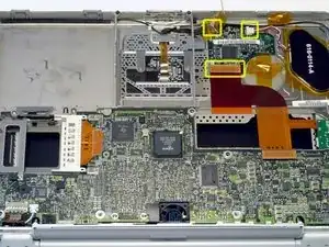
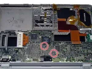
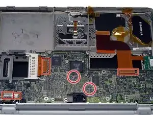
Disconnect the four indicated connectors from the logic board, removing tape as necessary.
-
-
-
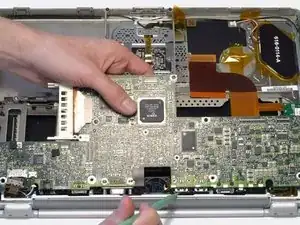
Carefully lift the logic board up and pull it away from you. The logic board may catch on the back panel ports liner. If this occurs, use a spudger or non-metal tool to free the logic board.
-
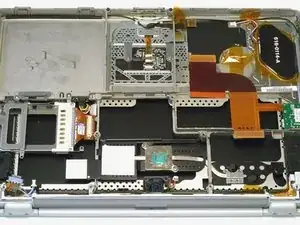
Remove the logic board from the computer.
-
-
-
Position the display at a 45 degree angle and rest the computer on a cloth with the back panel ports facing up. Remove the two T8 Torx screws from each clutch cover.
-
-
-
Close the display and pull off both clutch covers. You can use a non-metal flathead screwdriver if the clutch covers do not come off easily.
-
-
-
Open the display to a 90 degree angle. Rest the trackpad face down on the work surface and allow the display to hang over the edge. If possible, adjust your chair or work surface height so the display will rest on your legs and the upper case will lie flat on the work surface. If you cannot make this adjustment, you can remove the display with the screen closed. We recommend removing the display with the screen open in order to avoid changing the position of the hinges once the display has been removed.
-
-
-
Lift up the metal brackets on either side of the upper case.
-
Disconnect the inverter cable and carefully thread it through the slot in the upper case.
-
-
-
Carefully thread the display and backlight cables individually through the slot in the upper case. Be very careful with the display cable and it is easily damaged.
-
Remove the display assembly.
-
-
-
Remove the single black T8 Torx screw from the right side of the upper case.
-
Disconnect the orange ribbon cable that connects underneath the inverter board.
-
-
-
Lift up on the grey plastic framework enough to allow the inverter board to pass through. Be careful not to lift too far, or you may break the framework.
-
Remove the inverter board by sliding it up and to the right.
-
To reassemble your device, follow these instructions in reverse order.
