Einleitung
Your optical reader is broken because you are sure the DVD is facing the correct way and the TV is in the correct setting. This may happen due to overuse or manufacturing defects and this guide can help with optical drive disassembly and replacement.
Werkzeuge
-
-
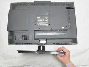
Lay the TV flat with the screen facing down.
-
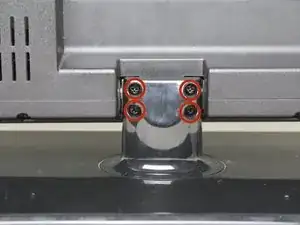
Remove the four, 12mm Phillips #2 screws from the back of the TV stand. Support the TV from underneath as you remove the screws, so the bottom does not fall on the table.
-
Remove the stand by lifting it away from the TV's backing.
-
-
-
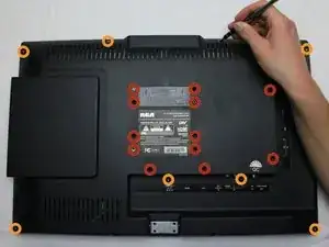
Remove the twelve, 6mm Phillips #2 screws from the middle of the TV's rear casing.
-
Remove the seven, 9mm Phillips #2 screws from the outer edge of the TV's rear casing.
-
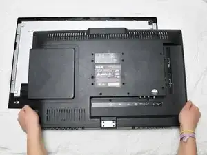
While holding the screen down, pull the back panel up slowly, ensuring that you do not forcibly disconnect the remaining ribbon cable.
-
-
-
Position the television to where the back panel is resting on the table and the screen is vertical.
-
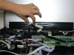
Peel the tape covering the ribbon cable horizontally.
-
-
-
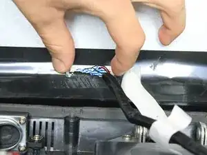
Pinch the clamps on both sides of the ribbon cable casing to detach it from the screen panel.
-
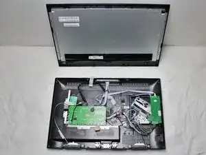
Remove the screen to isolate the back panel.
-
-
-
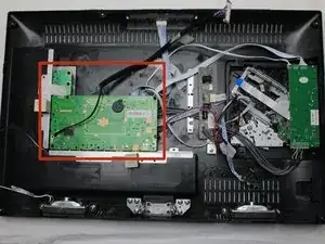
Identify the motherboard in the rear casing.
-
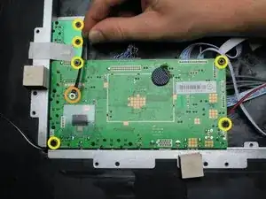
Remove the ground cable from the motherboard by gently lifting it up as shown.
-
Remove the six 6mm Phillips #2 screws from the perimeter of the motherboard.
-
-
-
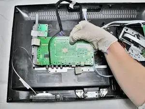
Remove the motherboard by gripping the rubber stopper as shown and lifting the motherboard up out of its plastic housing.
-
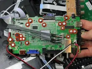
Carefully flip the motherboard over and locate the nineteen capacitors.
-
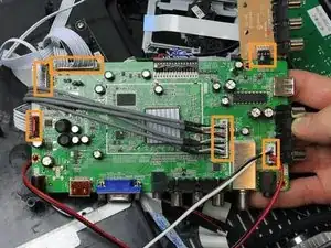
Notice the six cables attached to the motherboard. Pull on each cable connector with moderate to heavy force to remove them.
-
-
-
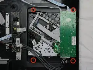
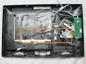
Remove the four 11mm Phillips #2 screws from each corner of the DVD drive plastic casing.
-
Untuck the cable consisting of five gray wires from underneath the black circuit board.
-
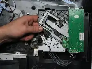
Lift the DVD drive up out of its plastic housing as shown.
-
-
-
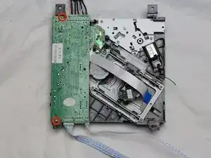
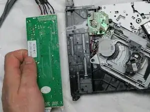
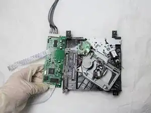
Remove the two 6mm Phillips #0 screws from the green circuit board.
-
Lift the circuit board up to remove it from the rest of the DVD drive.
-
-
-
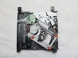
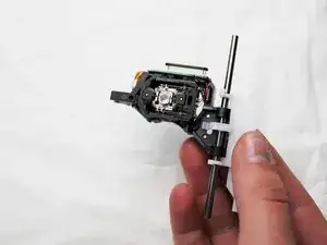
Remove the three 11mm T6 torx screws from the ends of the optical reader railings.
-
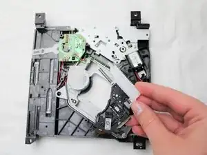
Lift the railings and optical reader out of their metal housing.
-
To reassemble your device, follow these instructions in reverse order.

Do you like playing game? What kind of games do you usually play? If you want to find a new game that is still very familiar, try play solitaire.
Lisa Sarah -