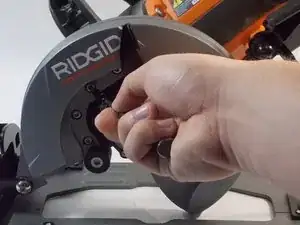
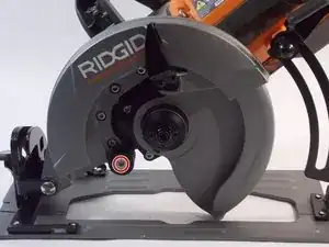
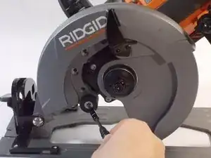
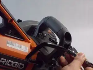
Einleitung
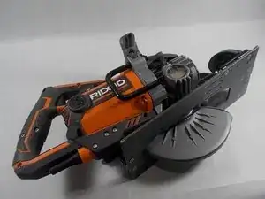
If your saw experiences any unnecessary vibrations or produces strange noises, the motor bearings are the main issue. Use this guide to help replace these motor bearings. All that is required to complete this replacement are a Torque 20 Screwdriver, Torque 50 Screwdriver, and Flathead Screwdriver.
Werkzeuge
-
-
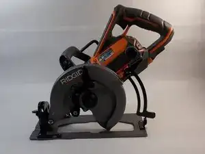
Place down the Worm Drive Saw on a sturdy surface.
-
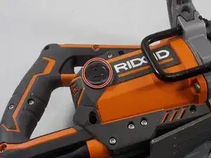
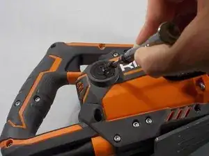
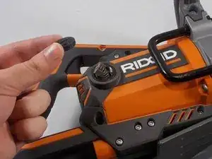
The motor brush cap is located on the side of the main housing assembly, it can be identified as a large black plastic cap with a slit running down its surface.
-
-
-
With the cap removed, the motor brush should now be accessible.
-
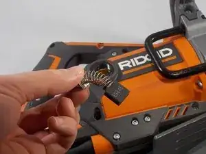
Carefully remove the motor brush by sliding it out of the main housing assembly.
-
-
-
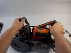
Maneuver the RIDGID saw, in order to easily remove the upper blade guard assembly.
-
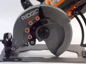
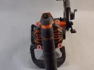
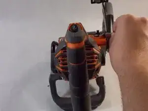
Using the T20 Torx Screwdriver, remove the four 4/10 cm screws that attach to the gear box.
-
-
-
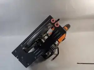
Using the T20 Torx Screwdriver, remove the two 4/10 cm screws that attach to the handle of the device.
-
-
-
Maneuver the saw to get to the base plate.
-
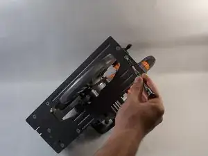
Using the T20 Torx Screwdriver, remove the two 4/10 cm screws that attach the upper blade guard’s base plate to the main housing assembly.
-
-
-
Using the T20 Torx Screwdriver, remove the four 10 cm screws that attaches the main housing assembly to the gear box.
-
-
-
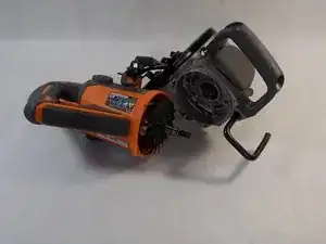
Wiggle out the gear box to easily gain access to the motor rotor.
-
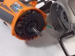
Once taken out, the motor rotor is easily accessible.
-
-
-
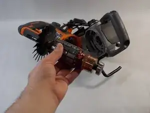
The motor rotor is lodged in between the armature and can be identified as a rod containing a fan blade.
-
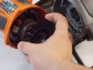
Carefully remove the motor rotor from the device.
-
-
-
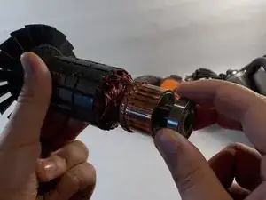
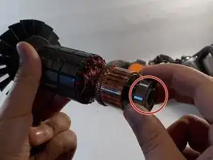
The bearings are located on the opposite end of the motor rotor, from where the fan blade was.
-
Carefully remove the motor bearings from the motor rotor.
-
To reassemble your device, follow these instructions in reverse order.
