Einleitung
Werkzeuge
Ersatzteile
-
-
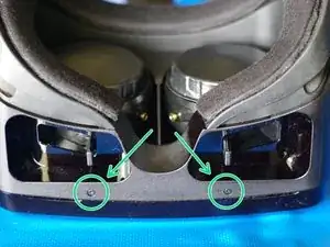
Lay HDK headset face down on a soft surface. Remove the two Phillips #00 screws from the bottom.
-
-
-
Turn the headset upright.
-
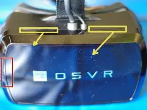
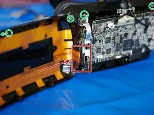
Behind the red box is a connector between a ribbon cable attached to the faceplate and a ribbon cable wrapped inside the body of the HMD. It's taped together in addition to the force of the connection, but is still somewhat fragile, so when opening, this left side should be treated as the "hinge".
-
There are now only two pairs of magnets at the top in the corners holding the faceplate to the body of the HMD. (In the inside image, one of the faceplate magnets is not pictured.)
-
There are two grooves on top, marked, to use in faceplate removal. Keeping in mind the minimal force holding the faceplate on, and the location of the faceplate connector, gently pull/fold the faceplate out and to the left. Do not use any tools for this step!
-
-
-
Install the STLink/V2 Drivers
-
Install the ST Tools Set (Including STVP)
-
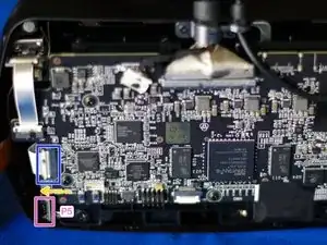
Locate the P5 4 PIN Connector on the Lower Left of the HDK.
-
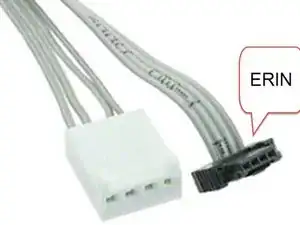
Connect the "ERNI" Connector (black part) to the P5 connector and connect the other end to the STLink/V2
-
Connect the STLink/V2 USB Cable to the HDM side USB.
-
Connect the HDM to the BeltBox and connect the USB and Power Adapter to the belt box.
-
-
-
Open ST Visual Programmer (STVP)
-
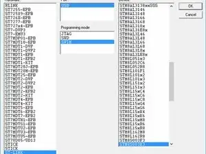
Select ST-LINK as the HARDWARE
-
Select SWIM as the Programming Mode
-
Select STM8S003K3 as the Device
-
-
-
Select "PROGRAM DATA" in the bottom
-
Click on "FILE > OPEN"
-
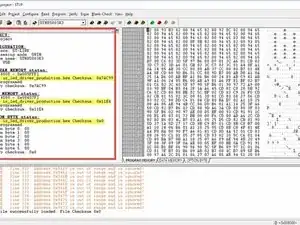
Select "ir_led_driver_production.hex"
-
Change the TAB to "DATA MEMORY"
-
Click on "FILE > OPEN"
-
Select "ir_led_driver_production.hex" again.
-
Repeat for "OPTION BYTE"
-
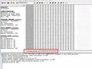
You should see the file in the "Status" tab on the left.
-
-
-
Click "Program > All Tabs"
-
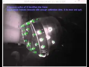
If there's no Error, disconnect the P5 connector, restart the headset and check into "VideoCalibrationUtility.exe" (Normally in the "OSVR-Core/bin" Folder) that you can still see LED.
-
If you do see the LED, do a calibration.
-
If you don't see the LED, make a post on Reddit, we will try to help.
-
To reassemble your device, follow these instructions in reverse order.
3 Kommentare
Looks nifty - though why STVP? The stm8flash utility used in the ir-programmer bundles can do all the same stuff, plus it's open source (GPL) and freely redistributable, and it's scriptable so it can be made very easy to use through automation. Pretty sure stm8flash can save the flash/eeprom too, which is probably not a bad idea to add to the script.
You can get the bundles on the IR driver releases page https://github.com/sensics/IR_LED_DRV/re... , but since the bundle contents themselves were all open source and in a git repo locally anyway (and there's an extra script that doesn't get added to the bundles, that actually does the work of making the zip and self-extractors), I just pushed them here: https://github.com/sensics/IR-Board-Prog... The script also takes care of splitting the hex file into "program flash" and "eeprom" (using srecord) on the fly, since all the tools want those separate but they get built (and are easier to keep together) as one hex.
(Oh, and FYI, I've got some other folks who I've suggested add to a guide or start a guide similarly, so don't be surprised if you see contributions roll in :D)
If it can work with the STM8FLASH, I would use that instant of STVP (it's more complicated). I didnt try STM8FLASH with the Official ST-LINK/V2.
It's okay to have contributions, I made this to help, but I'm not a "Instruction guy" :P
