Einleitung

You must remove the battery, the front, and the rear casing before removing the flash assembly.

  1. kOvDTMFpOTGOStDJ
    kOvDTMFpOTGOStDJ
    Nuqe5bDwjKLmoVHK
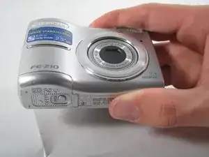
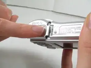
    • The battery compartment is located on the bottom side of the camera. Push the button in, and slide the cover to get access to the batteries.

  2. ZxDN3K3hyTgvRvcK
    ZxDN3K3hyTgvRvcK
    wsGTdrCIvwowmIhh
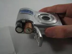
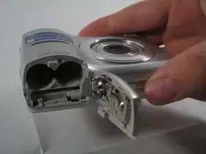
    • The batteries will slide right out.

    • When putting new batteries in, make sure they are pointing the right direction.

  3. QTG24NZNnPMtjEUx
    QTG24NZNnPMtjEUx
    6D5PieSOFZrdWTBq
    shaCqQuDKpQBitWU
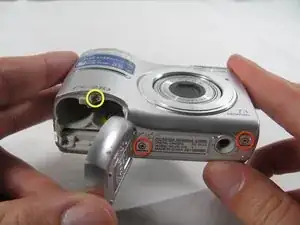
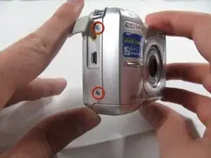
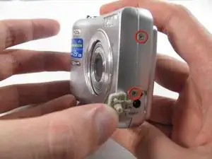
    • Remove the 7 screws holding the front case in place, with a #00 screwdriver.

    • Six screws are 3.6 mm.

    • The seventh screw is 3.2 mm.

  4. YF6x1BMOOIBUQGe2
    YF6x1BMOOIBUQGe2
    tRqkWaMDI2HQUXOc
    FWYixyCSqlGcMJnL
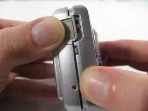
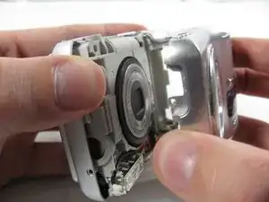
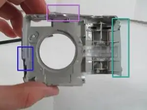
    • Pulling the front case off, requires applying enough strength in the right areas.

    • The front case snaps into place in three places:

    • At the top and bottom of the battery side (opposite of side pictured) of the case.

    • Right in the middle of the DC-in side (side pictured) of the case.

    • Top of the camera, to the left of the power button.

    • Once those places are disconnected, the front case will pop right off.

    • The camera in the first two pictures is upside down. This is the best position to place your thumbs to remove the case.

  5. 1tWeFSQXUwroXViL
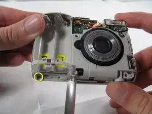
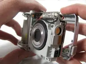
    • Remove the 3.2 mm screw in the battery compartment using a #00 screwdriver.

    • After removal of the screw the case will be loose, but do not tug it off. There is a cord connecting the rear controls to the motherboard.

  6. DBA1PkBHibHc1OUm
    DBA1PkBHibHc1OUm
    cIsDJRFKfEYBCv4R
    npYESMXiQalacGtK
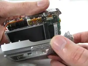
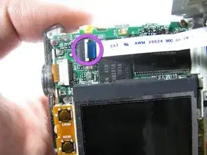
    • Carefully pull the rear case away from the camera until you have access to the cord connected to the motherboard.

    • Lift the white latch using a fingernail or a spudger.

    • Pull the cord from its connector.

  7. iQ6PwoO3hogHpH5d
    iQ6PwoO3hogHpH5d
    IFTgwjDBbYEw6aXK
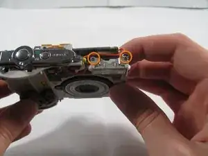
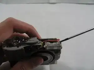
    • Remove the two 2.7 mm screws using a #00 screwdriver.

  8. u56pESfpkIjOv2qg
    u56pESfpkIjOv2qg
    XLSdZLA3RyBcB33b
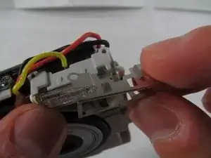
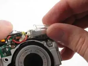
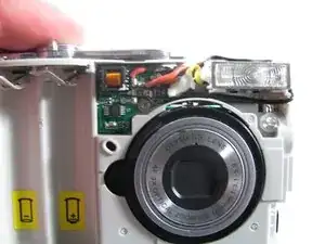
    • Remove the metal casing on the flash, by grabbing with two fingers and pry it off the snaps connecting it to the flash.

    • Remove the plastic cover on the flash, by simply grabbing the plastic with two fingers and pulling.

  9. KTOAvMXA5vhUnDFB
    KTOAvMXA5vhUnDFB
    D5DHXMiEIVidlWKJ
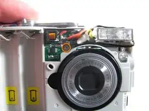
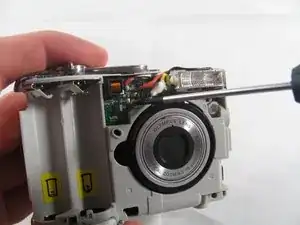
    • Remove the 2.7 mm screw holding the front circuit board in place.

  10. EfWwAgMxAwqSDgpZ
    EfWwAgMxAwqSDgpZ
    EvZdxWHoDA3D2qdJ
    AjPgvDQGSTnHs4RU
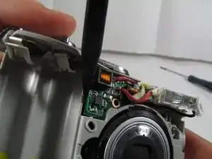
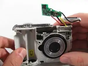
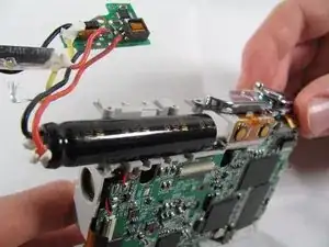
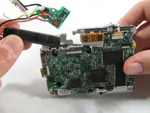
    • Remove the circuit board by prying it out with a spudger.

    • Remove the flashbulb from its place.

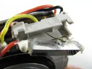
    • When taking out the flash bulb, be sure to carefully remove the wire taped to the back of the bulb (as shown in the second image). Gently separate the tape and the wire.

  11. SYlFkXavJKwHeAkR
    SYlFkXavJKwHeAkR
    fYcjOGtWPJ3lfDyd
    TObnMWlP4ALrydxm
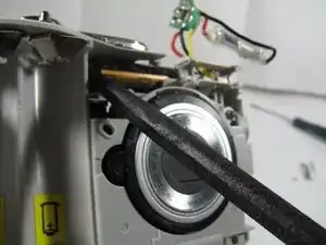
    • To remove the capacitor you must slide it out from the sticky tape that is holding it in place.

    • First insert a spudger between the capacitor and the plastic.

    • Pry with the spudger or pull with your hands to loosen the capacitor.

    • Capacitors can contain a lot of energy. If you touch the terminals you could get a strong shock. So be careful to avoid the terminals with your fingers and don't use any metal tools to interact with the capacitor.

    • The capacitor can be difficult to loosen at first, give it strong pulls and pushes and it should come out.

Abschluss

To reassemble your device, follow these instructions in reverse order.
Matt

Mitglied seit: 26/01/11

781 Reputation

0 Kommentare