Einleitung
-
-
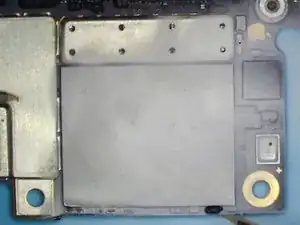
First, run cosmetic inspection of the motherboard. The motherboard is not deformed or water damaged.
-
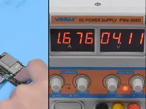
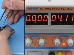
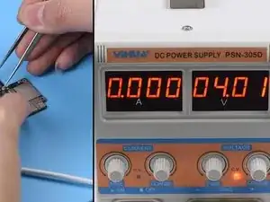
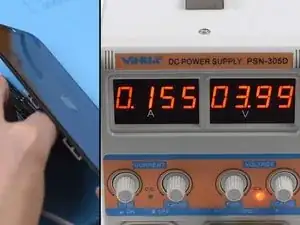
Connect the battery connector with the DC Power Supply. Get the motherboard booted up with tweezers. The boot current is larger than normal value. Judging by this, the three main power supply rails, PP_VDD_MAIN PP_BATT_VCC and PP_VDD_BOOST are in normal condition. The fault is probably related to the 17 power supply rails outputted from PMU.
-
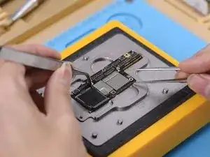
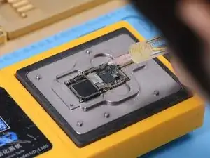
Now we need to separate the motherboard and confirm whether the fault is related to the upper layer or the lower layer. Place the motherboard on the specialized Heating Platform. Power on the heating platform and set the temperature at 160℃.
-
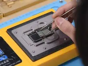
With temperature of the platform reaching 160℃, try to push the upper layer with tweezers. With the upper layer being loose, pick up the upper layer with tweezers carefully.
-
-
-
Now we can test the upper layer. Connect the battery connector on the upper layer with the DC Power Supply. Get the upper layer booted up with tweezers. The boot current is still larger than normal value. We can confirm now that the fault is related to the upper layer. Our next step is to check the 17 rails one by one.
-
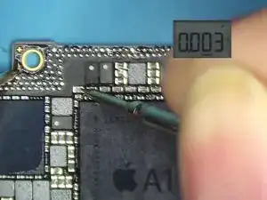
Let's start with PP_CPU_PCORE. Locate C2701, one of the test points of PP_CPU_PCORE on the bitmap. Run diode mode measurement of a capacitor on C2701 relevant circuit. The measured value is normal.
-
Continue measuring test points of the remaining 16 rails. Judging by the measured value, PP3V0_NAND has shorted. Since there are many components on PP3V0_NAND, we can locate the faulty component with rosin detecting.
-
-
-
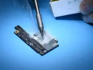
Dip some rosin with the Soldering Iron at 350℃. Then smoke rosin on components on PP3V0_NAND.
-
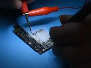
Set the output voltage of the DC Power Supply at 3V and get the black probe grounded. Meanwhile, get the red probe touched with a capacitor on PP3V0_NAND. Please be noted that the red probe shouldn't stay too long on the capacitor.
-
We can see that rosin on C2649 melts immediately. Judging by this, C2649 has been damaged. Let's try to detach C2649 from the board
-
-
-
Attach the upper layer to the PCB Holder. Remove black adhesive around C2649 with QUICK Vertical Wind Hot Air Gun at 260℃, air flow 2. Then detach C2649 from the board. Again, get the red probe grounded. Touch the two pins of C2649 with the black probe. The measured value is normal.
-
We can confirm now that the shorted condition is caused by damage of C2649. Still, we need to test the upper layer. Remove the upper layer and clean with PCB Cleaner. Connect the battery connector on the upper layer with the DC Power Supply. Get the upper layer booted up with tweezers. The boot current is normal this time.
-
-
-
Next thing we need to do is to solder the two layers together. Before soldering, we need to remove heat insulation adhesive on the lower layer. Then clean with PCB Cleaner.
-
Continue to place the lower layer onto the heating platform. Power on the heating platform. With temperature of the platform reaching 60℃, apply some Paste Flux to the third space PCB.
-
Then get the upper layer in position. With temperature of the platform reaching 150℃, push the upper layer with tweezers slightly. If the upper layer returns to the previous position automatically, then the soldering process is completed.
-
-
-
Power off the heating platform. Take the motherboard off the platform. Wait for the motherboard to cool for 2 minutes. Get the display assembly installed.
-
Connect the battery connector with the DC Power Supply. Get the motherboard booted up with tweezers. The boot current is normal. The phone comes with normal display. And can get access to the system. Fault cleared.
-
To reassemble your device, follow these instructions in reverse order.
