Einleitung
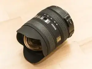
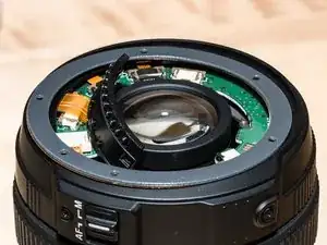
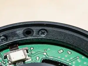
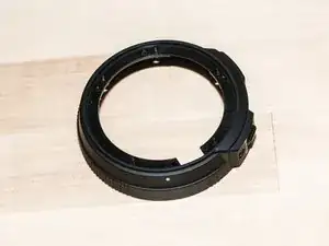
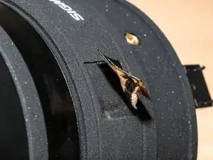
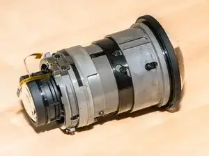
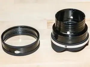
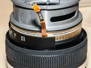
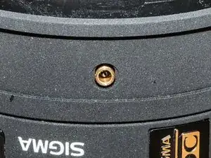
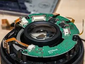
My favorite super-wide lens did not survive a five foot drop onto a concrete floor. (Nor did my camera, but that's another story.) This repair guide will show how to tear down the lens and repair a major structural component. It will also go deeper to show the zoom and focus mechanisms.
A word of warning about disassembling the autofocus mechanism - don't do it unless you A) really, really have to or B) are insatiably curious. Most of the repair guides out there usually end in the phrase "but my autofocus isn't working." Personally, I haven't figured out the secret to putting these suckers back together. The best I could do with mine is get it "kind of working". So, take that to heart, and let's get to it!
Werkzeuge
-
-
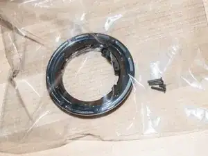
There are a guhzillion tiny screws and pieces in this lens. Get a bunch of ziplock baggies to hold each piece and its screws. Trust me on this.
-
-
-
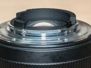
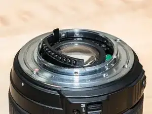
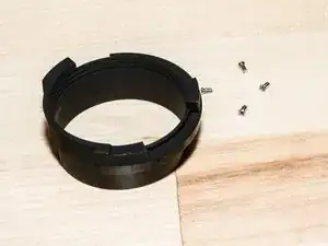
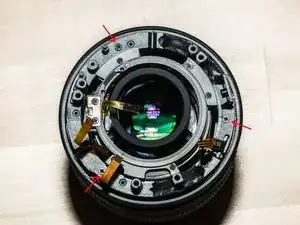
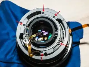
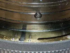
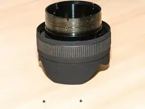
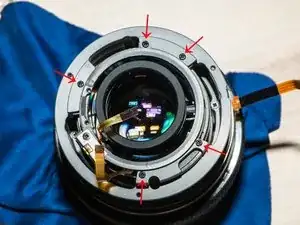
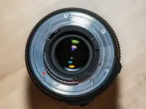
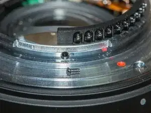
Remove the four screws holding the black center piece. There's one screw that sticks out a bit - no need to remove that one.
-
Remove the central black piece. The camera connector plate will hang loose for a while.
-
-
-
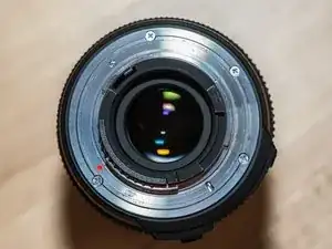
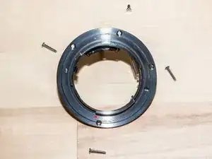
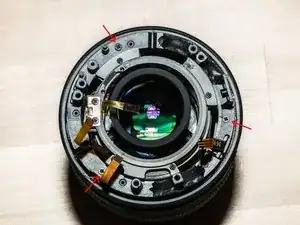
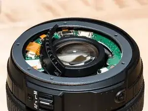
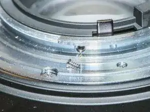
Remove the four screws holding the mounting plate. Lift off the mounting plate. (Photo shows inner components in place.)
-
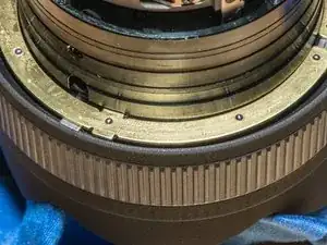
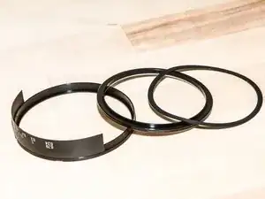
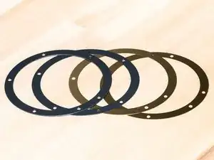
Remove the four spacer rings below the mounting plate. Be careful not to bend the brass rings.
-
-
-
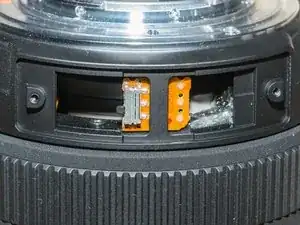
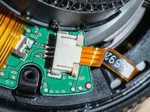
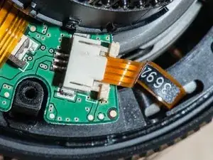
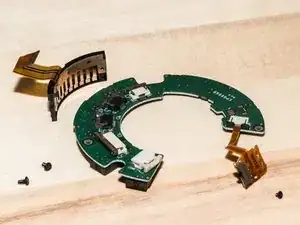
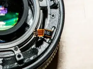
The ribbon cables are inserted into easy click connectors. Carefully pull out the retaining sliders and remove the cables.
-
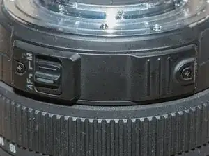
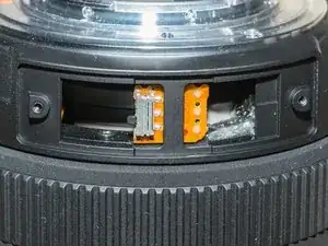
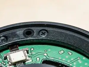
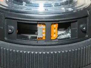
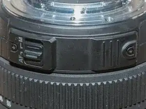
Remove the one screw holding the autofocus switch. Remove the switch. It's sticky on the back so it will take a bit of levering.
-
-
-
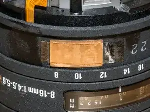
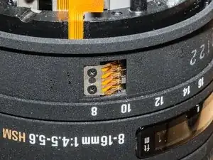
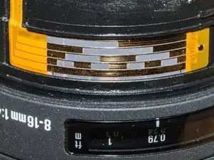
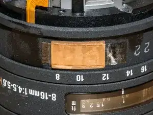
Peel off the copper tape covering the zoom encoder fingers.
-
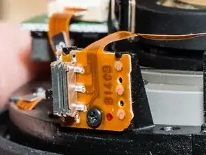
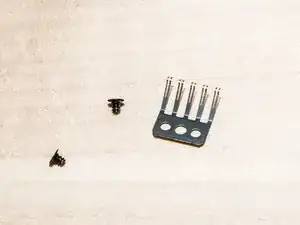
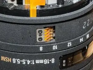
Unscrew and remove the zoom encoder fingers. Be careful - these fingers are very delicate.
-
-
-
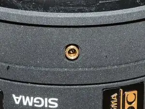
Remove the screw deep inside the brass zoom stop. Grab the zoom stop with tweezers. Wiggle it until it comes free.
-
If you want, or need to, you can remove the zoom ring. Rotate it and gently pull up until it pops off. Leave it in place if you can to prevent damage to the encoder.
-
-
-
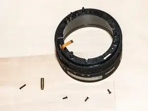
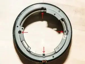
Remove the three screws around the outer ring. Lift off the zoom ring assembly. Don't snag the ribbon cables.
-
-
-
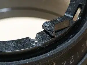
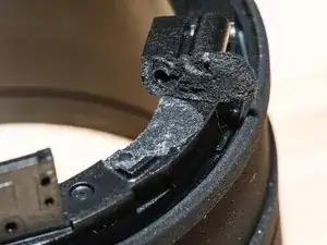
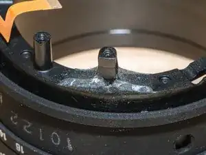
If the lens takes a hard hit, it is this zoom assembly that will probably break . In my case a couple of the support studs snapped off.
-
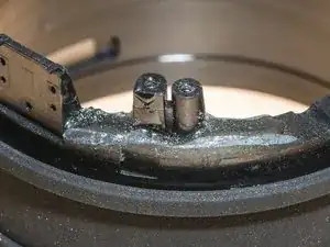
Glue any broken pieces with strongest epoxy glue you can find. Superglue is probably not a good choice because it won't handle any lateral knocks.
-
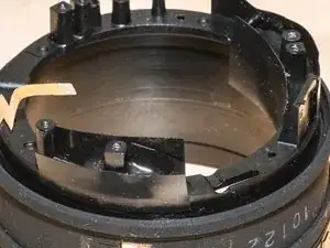
Be careful not to get glue where you don't want it. Use tape to keep the glue in place.
-
Put some weight on the assembly while the glue dries so that the repaired studs stay in position. If they are raised, even slightly, the lens alignment will be off.
-
-
-
Try not to get glue down the outer side of the support stud. Excess glue will interfere with reassembly later. If glue does get in the wrong place, carefully grind it down with a dremel tool once it hardens.
-
-
-
The next step will free the lens unit from the focus barrel. If you don't properly support that big, bulbous, expensive front element it will fall clunk to the table top.
-
Take a blob of plasticine or playdough about the size of a tangerine. Stick it into a baggie (baggies are your friend!) and mold it into a flattened ball with a dent about the size and shape of that big front element.
-
Take a clean lens cloth and lay it on top of the baggie. Nestle your lens into the dent. The plasticine should support the entire lens off the table. I.e., the lens hood should not be touching the table.
-
-
-
The screws holding these pieces together are in there very tightly. Make sure your screwdriver has sufficient 'bite' or you will strip the head (and then you're in deep trouble). You may also have to push down quite a bit to get the screws to turn. Find a friend to hold the lens steady while you do this.
-
Unscrew the five screws around the top of the light gray ring. This will free the lens unit from the focus barrel.
-
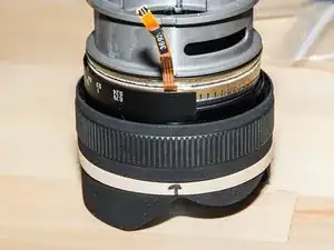
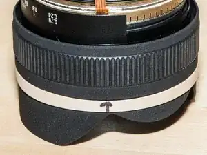
Put a tab of masking tape, or an elastic band, on the lens hood (not the focus ring). Mark the location of the ribbon cable. This will save you much grief during reassembly.
-
-
-
Remove the four screws from the inner base of the zoom ring housing. They will require some torque to get them out. Make sure your screwdriver has enough 'bite' and push down while turning. Get your friend back in to hold the barrel steady.
-
The housing will try to spring up; unscrew the screws evenly and apply some downward pressure on the housing as you remove the screws.
-
-
-
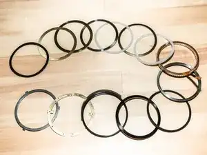
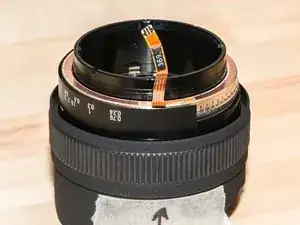
Remove all of the rings up to, but not including, the one with the F stop labels. It won't come off - don't force it.
-
With a small tipped tool, remove two of the three impossibly small plastic tabs from the barrel. Don't remove the one behind the F-stop label - it's a right pain to put back in.
-
Remove the remaining rings including the brass clutch plates.
-
-
-
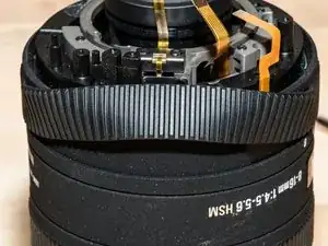
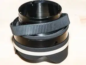
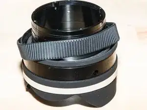
Remove the rubber focus grip. The focus grip is not interchangeable with the zoom grip. The focus grip has slightly finer "fingers".
-
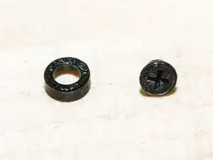
Remove the three screws and their bearings from the focus ring.
-
Pull the focus ring straight up to remove.
-
-
-
This teardown doesn't go any further. Go ahead and disassemble the lens unit if you dare.
-
Reassembly is tricky; the remaining steps will help you put it back together again.
-
-
-
Drop on the focus ring and replace the screws and bearings. Flip the bearing rings so that they nestle into the screws.
-
Slip on the rubber focus grip. Use the one with the finer ribs.
-
-
-
The order of assembly, from bottom to top is:
-
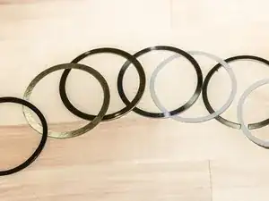
Steel/plastic, brass clutch plates, focus indicator, black plastic, thin rubber, rotor (thick black), stator (funky brass thing with a ribbon cable), fiber, split steel, fiber, steel (no split), thick brass, thin brass, spring.
-
-
-
Insert the ring that is steel on one side and black plastic on the other. Plastic side goes down. Engage the tabs into the focus ring.
-
Drop in the clutch plates and engage the inner tabs into the central barrel. Be careful not to lose the tiny ball bearings in the plates.
-
-
-
Drop on the focus indicator ring. There are shallow indents on the bottom that engage the tabs on the bearing plates. (Shown here in an assembled state.)
-
The ring can go on two ways. Make sure the numbers are on the same side as that mark you made earlier.
-
-
-
Drop on the black plastic ring and rubber ring . The rubber ring should nestle nicely into the plastic ring.
-
The focus label should be on the same side as the mark on the lens hood.
-
The rotor is the moving part of the ultrasonic wave motor. It's the metal ring that's black on one side, shiny on the other. Drop it on with the shiny side down. (Sorry, no picture.)
-
-
-
The stator is the fixed half of the ultrasonic wave motor.
-
Insert the impossibly small plastic tabs into the main barrel. These hold the stator in the correct position.
-
Drop on the stator with the wire pointing up. There are indents on the inside that line up with the impossibly small plastic tabs.
-
The stator will go on three ways. Make sure the ribbon cable aligns with the mark you made earlier.
-
-
-
Drop on the remaining rings in this order:
-
Fiber ring, split metal ring (it has a little tab that engages into the barrel), the other fiber ring, solid metal ring, brass rings, spring. (Apologies for the crap picture.)
-
-
-
Drop the focus assembly onto the main lens module. Be careful with the ribbon cables.
-
Align the five screw holes. Secure with screws.
-
-
-
Drop on the zoom assembly. Carefully thread the focus encoder cable through the slot.
-
Align the screw holes and secure.
-
-
-
Rotate the zoom ring until the oval hole lines up with its mate on the lens module. Insert brass pin and secure with a screw.
-
Reattach the zoom encoder fingers and copper tape.
-
Replace the rubber zoom grip.
-
-
-
Reinstall the circuit board with the two screws.
-
Replace the zoom switch.
-
Insert all ribbon cables and firmly (but carefully) click the connectors in to place.
-
Insert the camera connector cable and click the connector.
-
-
-
Drop on the top cover and align with the screw holes. The large side fits over the zoom switch.
-
Secure with one screw. The screw hole is slightly deeper than the other holes.
-
-
-
Make sure the interior and exterior zoom switches are in the same position. They must line up when you replace the cover.
-
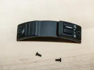
Replace the zoom switch cover and secure with two screws.
-
-
-
Replace the spacer rings. The brass rings go on the bottom, the thickest black ring is on top. The rings fit onto a tab that keeps them aligned. Make sure the holes line up with the screw holes in assembly below.
-
Drop on the mounting plate. The long leg goes inside the lens and into a hole in the central lens assembly; it's easy to see.
-
Secure the mounting plate with four screws. The shorter screw is directly opposite the red dot.
-
-
-
Attach the camera connector plate with two screws. These screws have a finer thread than the others.
-
Insert the black center piece. Secure with the remaining two coarse-thread screws.
-
Mount onto a camera and you're good to go!
6 Kommentare
Excellent detailed guide to the lens breakdown and rebuild!
wgholden -
did you recored a video doing all these steps !!?
Amer, no, I did not record a video. It was not as smooth a process as the pictures would suggest. There was much chaos figuring it all out.
