Einleitung
Werkzeuge
-
-
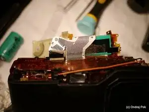
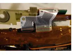
I decided I would try to design and order a small batch of flexible PCB as a replacement of the fragile ribbon - the achiles heel of all GR1's;
-
If anyone is willing to donate their dead GR1 for this project, I would try create the input data for the manufacturing of the flexible PCB (Gerber file) and order a small batch of PCBs. I would then make the files available open source.
-
So, Is anyone willing to donate the GR1 body? I am paying for the shipping and offer also one of the new ribbon PCBs as a reward.
-
Disclaimer: It is still just an idea, and I can't guarantee it will work. However if it turns out the way I hope, this could resurrect hundreds of crippled GR1's with failing LCD or VF lines.
-
-
-
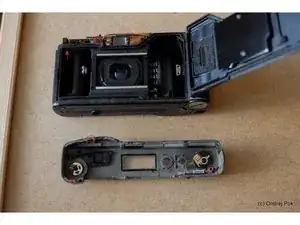
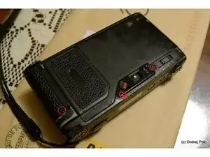
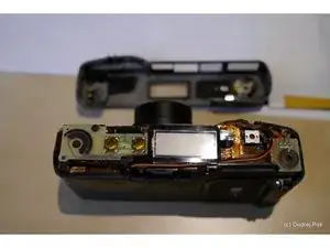
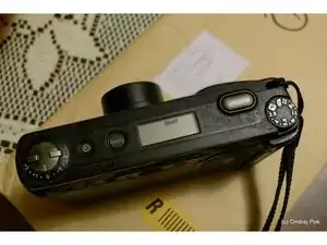
There are 4 Philips head screws that must be removed to open the top of the camera.
-
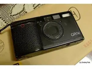
2 are under the leatherette, one on the front and one on the back
-
be careful when removing the plastic piece around the eyepiece, there is a hook holding the right hand side farther from the visible screw.
-
There is also one long screw accessible from the inside near the film take up spool.
-
-
-
You will see the LCD and a bunch of flexible circuit boards soldered on top of each other
-
To continue disassembly further you will need about 20-30W "pencil" soldering iron
-
If you want to replace the conductive tape and restore lost segments of the top status LCD or viewfinder icons, you will also need a "3M Electrically Conductive Adhesive Transfer Tape 9703" (product page) Usually can be bought on ebay in smaller quantities.
-
Buttons should stay with the top cover as can be seen in the picture without anotations
-
-
-
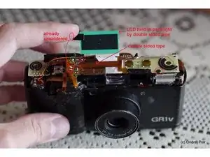
There are some connections you need to desolder and one screw you need to remove.
-
the red circled solder joints may need to be desoldered (see comments below guide), I am not sure about the green circled, but try not to if possible
-
the flexible circuit board is held by strong double sided tape and it might appear that you need to desolder more joints, when it's actually just the tape holding it.
-
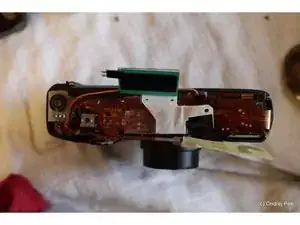
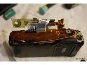
Your goal is to get to state like in the second picture, where I've bent the flex circuit boards open to gain access to the white flexible ribbon cable
-
-
-
This is the hardest part, and it's very difficult to take pictures of or describe.
-
you need to somehow gently detach the white ribbon cable from the LCD / flexible circuit board / viewfinder LCD (replacing ALL 3 conductive tapes may not be necessary, see comments below guide)
-
The ribbon is very fragile, and in all those connections is covered with a transparent tape to add strength to the connection
-
Be sure to clean both surfaces with alcohol and remove any residue of previous conductive tape
-
Before reattaching simply cut appropriate size of new conductive tape and apply to the ribbon, then press in the right place
-
reattaching to the flex circuit board is the easiest, because you actually see the copper paths which need to align with the black stripes of the ribbon
-
reattaching to the viewfinder LCD is more difficult, you need to align the right hand side edge of the ribbon
-
reattaching to the LCD is by far the hardest. On the LCD itself you can just barely see the conductive paths when you look at an angle. They are made of ITO (Indium Tin Oxide) and nearly transparent. I made marks where the rightmost and leftmost condctive paths are with a sharpie on the other side of the glass, and then glued the ribbon back on
-
-
-
If you've done everything right, you should see all segments on the the top LCD and in the viewfinder
-
it took me several tries to reattach the ribbon to the LCD and viewfinder LCD, patience and steady hands is the key to success.
-
Try not to damage the ribbon too much when detaching it. I did and had to shorten it slightly and in the end I had problem to fit the parts back together.
-
Reassembly should be just reverse order of disassembly. Don't forget the rewind button.
-
When you're at it, do yourself a favor and buy some leather sheets from Aki Asahi and give your GR1 a new covering.
-
To reassemble your device, follow these instructions in reverse order.
11 Kommentare
Dear Ondrej, first of all, thank You for the guide! I have repaired mine (GR-1s) successfully based on this. Only a few minor things:
1) I did not remove the LCD end of the ribbon (on the picture in step 4, left side, red circle just below the number "82")
If only the common end of the ribbon has the fault, it is enough to tear that one.
2) the worst part, that there is no 2nd chance, after somebody tear the ribbon. If the contacts broken at the end of the procedure... all the camera could go to the bin.
3) I did not unsolder the backlight part - not needed. Maybe there is some difference between the models (GR1s vs GR1v)
Gyuri
Heya! I have a GRi and I need to replace the shutter, any thoughts on where to find parts? I've been scanning ebay, but no luck.
cpnurse -
$@$* why the &&^& did I try this &&^&, it's a mess. &&^& your diy $@$* @%^$$@$.
diego_dm -


Happy to donate a GR1S (with this fault) if you are still looking.
Ollie Garside -
Hey Ollie, I still didn’t get a parts body to get precise scans of the flex ribbon and get a replacement manufactured. Please send me an email to ondrej dot pok at gmail
Ondrej Pok -