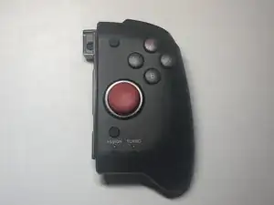
Einleitung
-
-
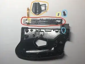
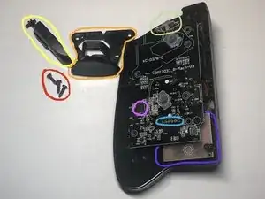
Lift the back half slightly off the front half and fold it open along the right edge.
-
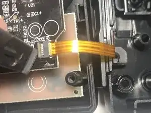
The ribbon cable is circled in the image.
-
-
-
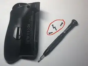
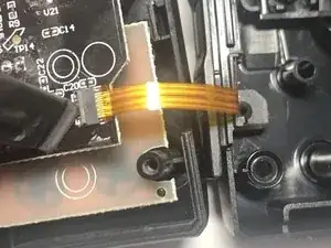
Use a plastic spudger to flip the ribbon cable latch up as shown in the first two images.
-
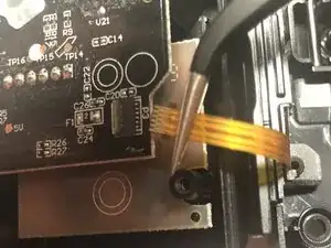
Remove the ribbon cable from the slot by pulling to the right with tweezers or fingers gently.
-
-
-
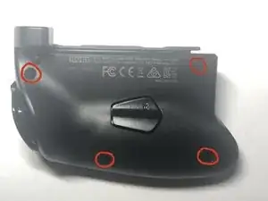
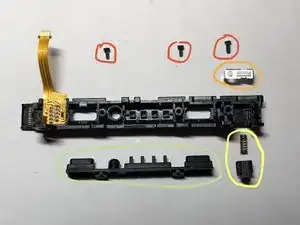
Remove one PH00 screw that is securing the rail to the back half.
-
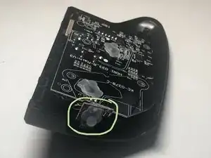
The FR button can be removed by placing a lever/spudger under the circled area.
-
The rail connector can be removed once the yellow circled screw is removed.
-
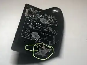
The button that releases the buckle lock can be removed after the rail and goes in the hole circled on the back half of the controller.
-
The one remaining screw (not marked) does not need to be removed as it only secures a bit of plastic.
-
-
-
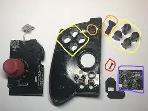
Remove the three PH00 screws.
-
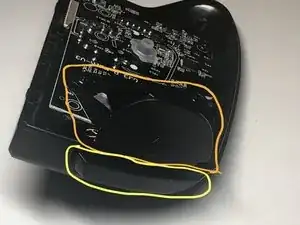
Pry out the metal cover over the buckle lock. Be gentle so as not to bend the metal.
-
The spring loaded buckle lock can then be removed. NOTE: Do not loose the spring when disassembling. Reassembly can be tricky because the spring needs to be compressed to get back in place.
-
The plastic cover over the holes in the middle of the rail can be removed. This is where the SL, SR, and connect buttons would be on a normal Joy Con controller and also the lights indicating which controller number it is.
-
-
-
The ZR button can be removed once the red circled screws are removed.
-
The R button is underneath the ZR button and is easily removed once the ZR button is out of the way. There is a small hole that one end of the R button fits into.
-
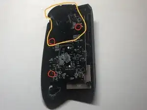
Remove three PH0 screws, two that hold the ZR button plastics and one on the top main board.
-
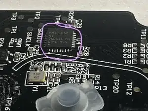
The processor for the controller can be seen on the top main board. See the details in Step 9??
-
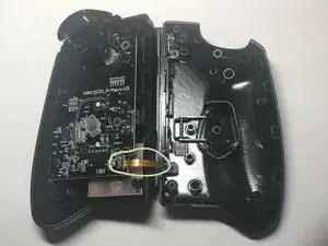
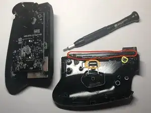
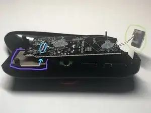
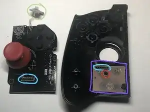
The connector between the top and bottom boards is shown here.
-
The bottom board on the right controller is small and only picks up the bottom three buttons which using a small 6 pin connector.
-
Warning: Do not try to remove the top main board before you remove this small button board in the next step.
-
-
-
The small R button board is slid into a slot and has delicate wires that connect it to the top main board.
-
Clasp on both sides of the small R button board with your fingers and wiggle it out.
-
The top main board is connected to the bottom board with a connector.
-
The bottom board is small and underneath the top main board.
-
-
-
Pull straight up on the top main board and the two boards will disconnect. The connection between them is circled in light-blue. Notice the joystick controller is on the top main board.
-
The bottom board is still secured with one screw.
-
Remove one PH0 screw.
-
Remove the plus (+) button.
-
Remove the X, A, B, & Y buttons.
-
The bottom board can be removed as well as the last rubberized bottom three buttons.
-
Notice that this top main board has the same processor as the main motherboard of the left controller. It is MM32L052NT which is a ARM Cortex(TM) M0.
-

To reassemble your device, follow these instructions in reverse order.
10 Kommentare
Hey there, thanks for having this guide made. I had an issue with the locking button not pushing in and Hori took 3 months to do nothing so I decided to see if I could fix it myself but because this guide was made I didn’t need to go in blind. Now it’s working and I can lock the controller into my Switch properly! Thanks again!
tribal -
So very glad that it could help you out. I’m just a normal user of iFixit; anyone can contribute. Find where there is a lack of guides and add one. Do your part for the right to repair!
What is the best method to reattach the ribbon cable in step 3 during reassembly?
Lay the two halves next to each other, lift the locking bar on the board-side connector, use tweezers to hold the cable (like in pic 3 of Step 3), insert the end of the cable into into the board-side connecter (make sure to insert it all of the way), then lower the locking bar.
Bonjour est-ce que quelqu'un serait quel module de joystick est utilisé je dois remplacer le mien car il a du drift merci
Allan -
Sorry, but I didn't get the joystick model number or anything when I tore it down. I hope someone else can help you out. However, if you look at the back of the board, the layout of the pins is similar to older xbox controller joysticks.