Einleitung

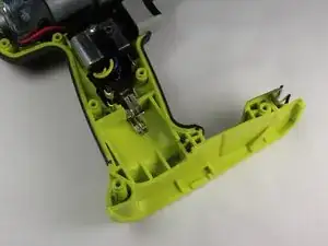
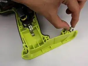
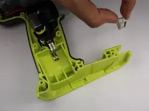
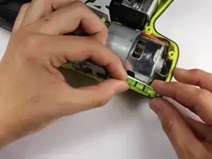
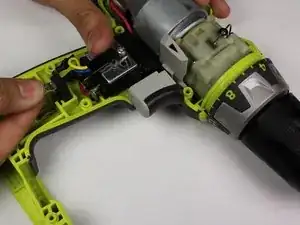
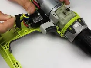
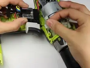
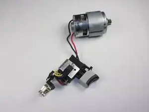
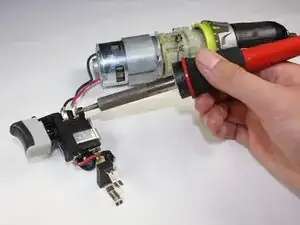
This guide details the process of removing the motor assembly from the drill. The process requires removing all of the internal electronics from the drill case. Due to the tight constraints of the wiring within the drill, reassembling the drill may require use of a spudger to push the wires out of the way of the case.

  1. nthDZunYT6Ay6ZLE
    nthDZunYT6Ay6ZLE
    oYAfykSaADf6oX4I
    pZ56BNLpZZduhM4B
    • The battery can shock you. Only touch plastic, non-conductive components.

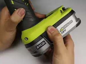
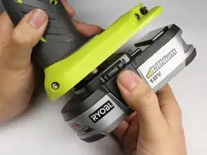
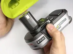
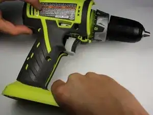
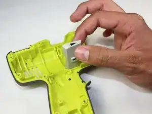
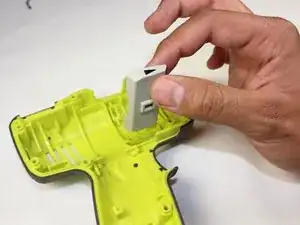
    • Detach the battery unit from the drill body by pressing the battery release buttons on both sides of the unit and pulling outwards.

  2. S5HRwRLOZTOZXNuC
    S5HRwRLOZTOZXNuC
    cwYGZYKkBNBHVKJH
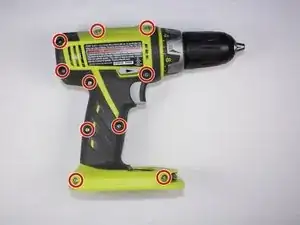
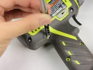
    • Use a Torx T10 screw driver to unscrew all ten 13.5 mm screws from the drill casing to gain access to the interior.

  3. iMEBELNaocJKErkq
    iMEBELNaocJKErkq
    Me4OaE1Cv6jwL4pl
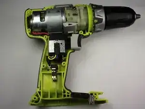
    • Gently lift the casing from the drill body.

    • Take the casing completely off the drill body to gain access to the interior of the drill.

    • The Ryobi P202 casing has Part #: 200690001

  4. nrkFmblAsX4hv1Hw
    nrkFmblAsX4hv1Hw
    EDOVGv6c1NgwUCua
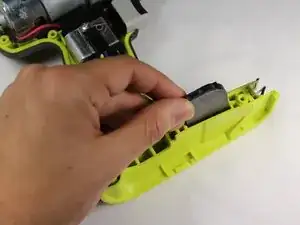
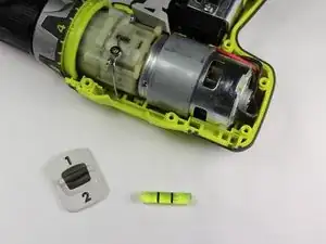
    • Gently lift the magnetic tray from the bottom of the drill body.

    • The magnet is Part #: 303001015

  5. cQFqqxXMqOErXfyY
    cQFqqxXMqOErXfyY
    YPlLhZAisMcRjVlE
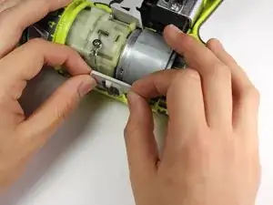
    • Grip the bit-clip and gently lift up to remove it from the case.

    • The bit-clip is Part #: 630206007

  6. eyhdZk3nr2QarMHR
    eyhdZk3nr2QarMHR
    jlj2LRFdMZ1PBGDC
    1O1D26AnuRa2RjZL
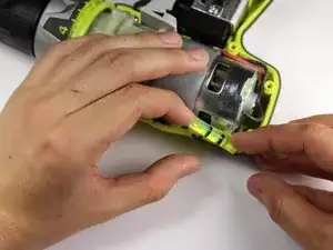
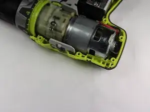
    • Rotate the Drill 180 degrees so that the top is facing you.

    • Lift the level gauge out from the top corner of the drill.

    • The level gauge is Part #: 3000909

  7. ArcbgGRdHGTW1PPB
    ArcbgGRdHGTW1PPB
    rMb4yJFP5dovGqed
    • Lift the gear switch upwards from the top of the drill head.

    • The gear switch is Part #: 341098001

  8. uSBYSqjUZITrbFZ4
    uSBYSqjUZITrbFZ4
    1jXaeUJ43fTaDvLu
    • Grip the battery clip and pull straight up to remove the metal battery contacts.

    • You can now clean the metal battery contacts with isopropyl alcohol.

  9. NEnXxaSInime1WEU
    NEnXxaSInime1WEU
    LdSa2nLROLikBGYS
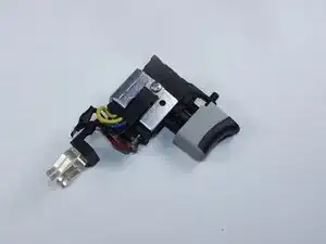
    • Holding the direction select switch in place, grip both sides of the trigger assembly and lift it up and towards the base of the drill.

  10. OOL4eiNMnEug4WBt
    OOL4eiNMnEug4WBt
    DOtxK5k6olGBQY6N
    • To separate the trigger assembly from the motor, use a soldering iron to melt the solder and pull gently on the red and black wires from the trigger.

    • Heating the solder may melt the plastic packaging. Prior experience with soldering is required.

    • The trigger assembly is Part #: 270001392

  11. UliPZWmBZpKL4xhA
    UliPZWmBZpKL4xhA
    tBeC3lBnBw2AUHJe
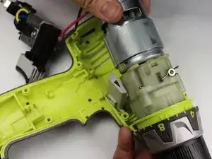
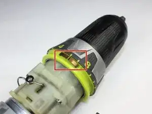
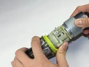
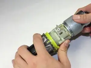
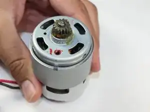
    • Gripping the rear of the motor and the chuck, lift up.

    • There are two copper springs that are attached to the front of the chuck. They may fall off when lifting the chuck, so be careful when doing so.

  12. GKhiDg3BrZLweVHB
    GKhiDg3BrZLweVHB
    Yq5NHYnrbWQ5ywdv
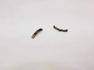
    • Remove the copper springs. There are two on the either sides of the chuck and are loosely placed in the chuck's grooves.

    • These springs are small and may fall off when you lift the motor up. Take note of the springs when doing so.

  13. 31VsSdPwVkdwsTii
    31VsSdPwVkdwsTii
    DLcBkF3TM3YxyHht
    • Lift up on the direction toggle to remove it from the case.

  14. nZfkpf65Fcyd4Dnm
    nZfkpf65Fcyd4Dnm
    sppcREqxBfM5rfCO
    yGAFEFRbWDPmxMPF
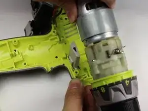
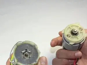
    • Hold the chuck and twist the motor clockwise and then pull apart to separate the motor from the chuck.

    • The chuck has a loose black washer that holds five gears in place. Be careful not to separate the washer.

    • When reassembling the chuck and motor, take note that the red wire in the back of the motor is farthest from the top of the assembly. In other words, the red wire should be closest to the trigger.

  15. 4KsIRSKWMuSR6Nck
    4KsIRSKWMuSR6Nck
    E1FVyuKolbtLBfkF
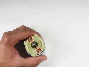
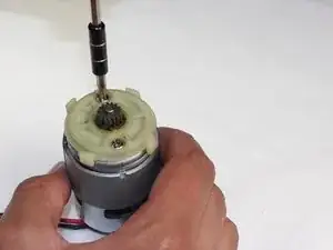
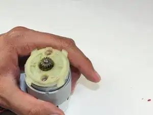
    • Unscrew the two 10mm Philips #1 screws to remove the plastic spacer. Be careful not to lose the metal ring washers that come with the screws.

  16. CIYY3PMRUCjaXHlb
    CIYY3PMRUCjaXHlb
    QBIkTT3DY5XHbiRO
    GHvISyegVxYXsPWn
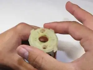
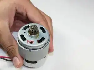
    • Remove the plastic spacer by lifting it straight up.

Abschluss

To reassemble your device, follow these instructions in reverse order.

Joseph Eckstein

Mitglied seit: 08/04/15

1575 Reputation

Ein Kommentar

How can I order the copper motor for P202?
Wilfredo. A. Burgos -