Einleitung

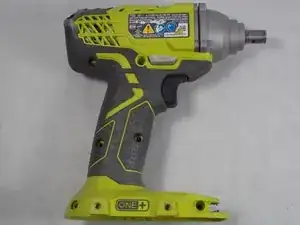
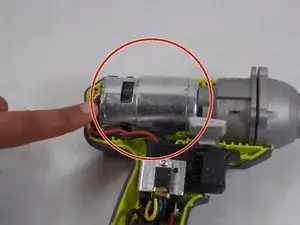
Use this guide to replace the motor in your Ryobi P235 impact driver if it is overheating or under powered when the battery is fully charged.

The motor is what converts the power stored in the battery to the physical power used to spin the cam shaft and hammer assembly. Since the motor requires the most steps and is the most difficult part to replace, it is important to keep an eye out for any cracked or broken components while taking apart your impact driver.

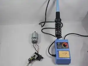
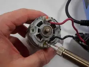
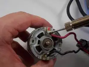
When you reach steps 12 and 13, the wires are soldered to the motor so a soldering iron will need to be used to disconnect them from the old motor and then reattach them to the new one.

  1. 5SLxTbksiTQW6LnR
    5SLxTbksiTQW6LnR
    OtRQ5FKLNPVREGaJ
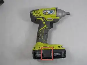
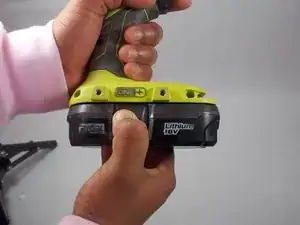
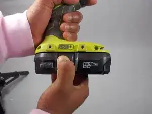
    • Push in both push tabs on the battery at the same time.

    • They are located below the green housing and are in the middle on both sides of the battery.

  2. XCyPZM6jqZheLVvU
    XCyPZM6jqZheLVvU
    cUkgQvhohIRjxSdE
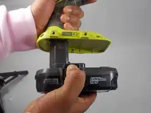
    • Pull the battery away from the drill housing while holding in both tabs.

  3. hlaDJ5vpZqPyTRJG
    hlaDJ5vpZqPyTRJG
    hHkxDbLi2QNNGrCA
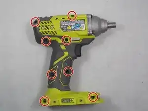
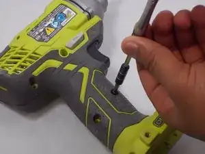
    • Use a Phillips #2 screwdriver to remove the eight 16 mm screws that secure the housing.

  4. yUArmUqFwKf22Rvi
    yUArmUqFwKf22Rvi
    wkZbJH1NbOcwHBKB
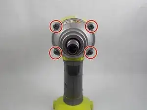
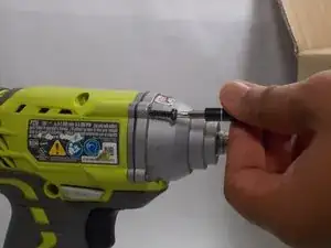
    • Use a T20 Torx screwdriver to remove the four 25.4 mm screws that secure the front of the housing.

  5. NH6XXeWBNKGhIGHJ
    NH6XXeWBNKGhIGHJ
    6LvJScWJFsGskGDE
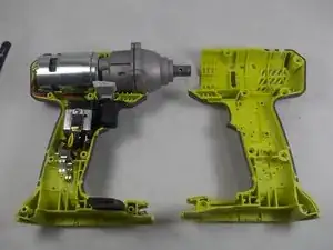
    • Open the housing with the data label facing up.

  6. wNCNhFwJnHy33ULD
    • Lift the motor and chuck assembly out of the housing.

  7. 1Il6HLLZRs15EaRu
    1Il6HLLZRs15EaRu
    i6HTElXKTKB6K6xM
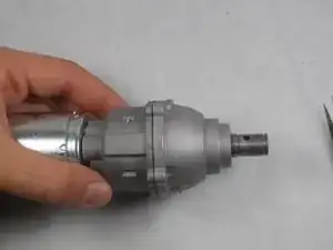
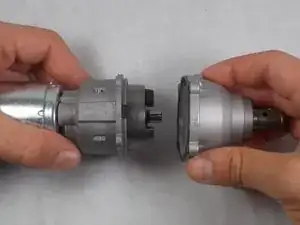
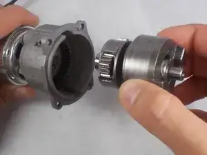
    • Remove the gear case and sleeve bearing assembly from the inner case assembly.

  8. huHG2EESa1XvUKeL
    huHG2EESa1XvUKeL
    n5CmJlX6nBVYJ1Gd
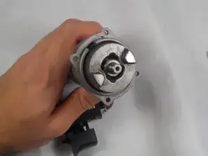
    • Remove the cam shaft and motor assembly.

  9. 1YvWJfHFOlJvvPUP
    1YvWJfHFOlJvvPUP
    xLY4TUwfD3p1HgL1
    ihZCVJssDTCYHRCS
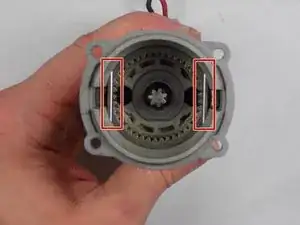
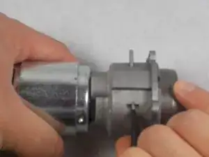
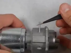
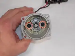
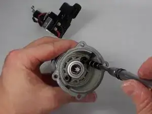
    • Remove the metal pins on each side of the inner case assembly.

    • It is easiest to push the pin through the opening from one side and once enough of the pin is through, grab it with the tweezers and pull it the rest of the way through.

    • When reassembling, make sure the pin goes in straight and makes it out the other side, rather than going in diagonally and into the inner case assembly.

  10. OgRLAbMeyOocVtjE
    OgRLAbMeyOocVtjE
    R5hb1nOHQRdRFkdc
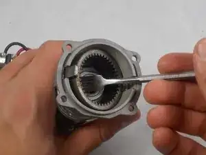
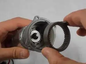
    • Remove the ring gear.

    • To help lift the ring gear out of the inner case assembly, wedge the spudger under one side, moving it up by a little, then switch to the other side and repeat until the gear ring is out.

  11. AmfK4vRRIuBe1ieW
    AmfK4vRRIuBe1ieW
    3yDUaRWQibcuDYxx
    FCFt5PmabiW1BYrK
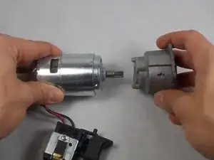
    • Remove the two 8mm screws and spring washers connecting the motor to the inner case assembly.

    • Separate the two parts.

  12. ytCZF6ESEFWooOrH
    ytCZF6ESEFWooOrH
    bQcBiFUJE24LLgGT
    HZKZPmrKLU1SiCh6
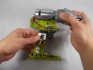
    • Use a soldering iron to remove the black and red wires connecting the motor to the trigger assembly.

    • Use the soldering iron to connect the new motor to the trigger assembly.

    • Make sure the red wire connects to the lead with the red mark on it.

Abschluss

To reassemble your device, follow these instructions in reverse.
Paul Sousa

Mitglied seit: 29/10/19

748 Reputation

0 Kommentare