Einleitung
For more information on replacing the main circuit board, please refer to page 25 in the service manual.
Werkzeuge
-
-
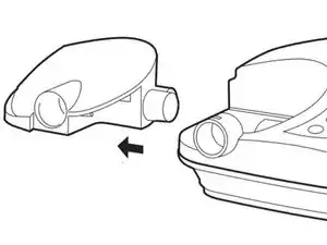
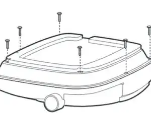
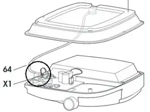
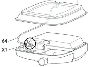
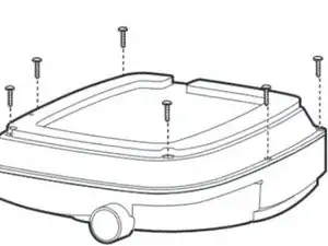
Remove the lower part of the housing with a swiveling motion away to the side. Note the SOMNOcomfort series uses a shorter circuit board than the balance series ventilator. (pg. 23)
-
-
-
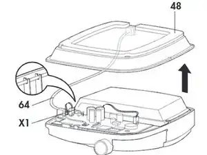
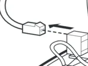
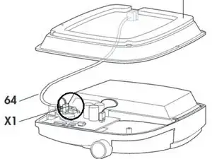
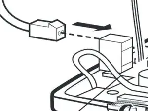
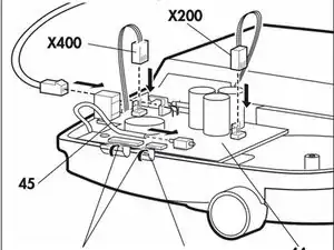
Remove the connector (X1) from the circuit board.
-
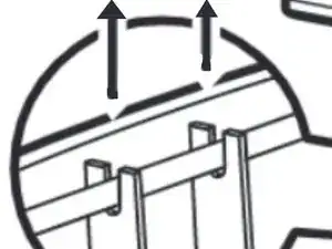
Pull the connecting cable (64) from its mount.
-
Now set aside the lower part of the housing. (pg. 23)
-
-
-
Next, how to close the compartment and reverse the process.
-
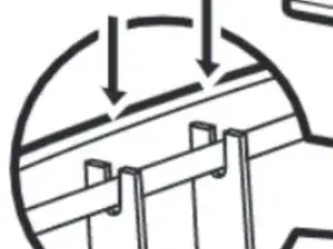
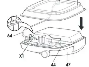
Hold the lower part of the housing to the upper part at an angle
-
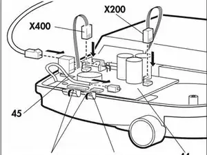
Attach the connector (X1) to the main circuit board. When doing so the connector’s nub has to point towards the lock. (pg. 24)
-
-
-
Properly align the main circuit board inside the unit.
-
Attach the connecting cable (64) to its mount (pg. 24)
-
-
-
Place the lower part of the housing on the upper part (47). Please make sure the main circuit board (44) is aligned properly, and that the connecting cable (64) is not being squeezed anywhere. (pg. 24)
-
-
-
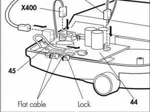
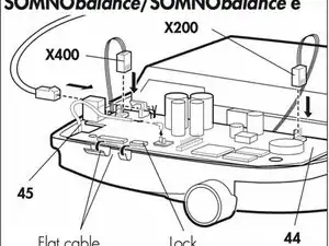
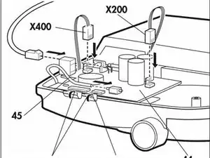
Remove the flat cables from front panel foil and display: To do so, pull the lock. Once you have pulled the lock, you can remove the flat cable.
-
-
-
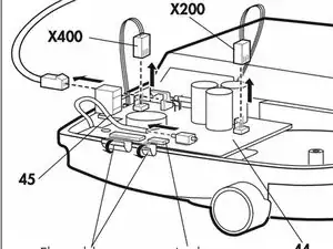
Remove pressure measurement tube 45 from the pressure sensor or pull out the tube adapter of the pressure measurement tube.
-
-
-
Attach tube 45 to the pressure sensor of a new main circuit board 44 or connect the tube adapter of the pressure measurement tube to the angular bush on the pressure sensor.
-
-
-
Reattach the flat wires of front panel foil and display to the main circuit board: – Pull the lock. – Insert the flat cable into the connector. – Push the lock back in.
-
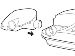
To reassemble your device, follow these instructions in reverse order.
