Einleitung

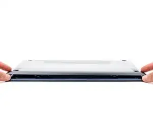
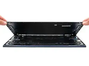
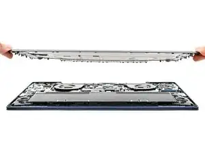
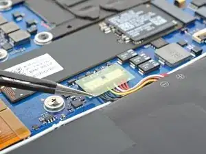
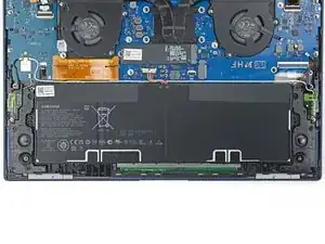
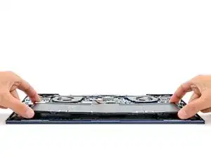
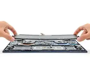
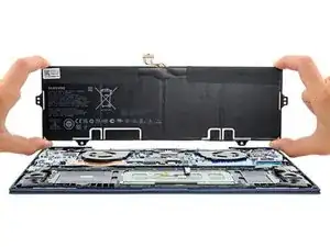
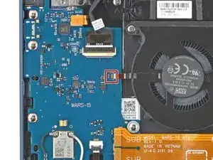
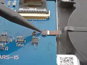
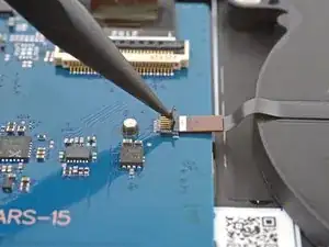
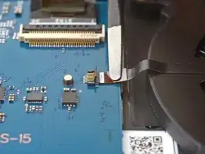
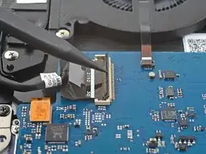
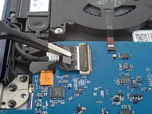
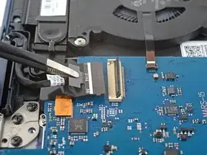
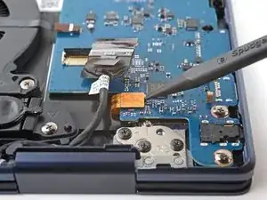
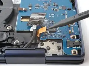
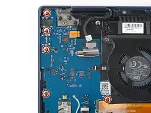
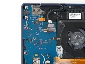
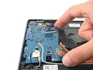
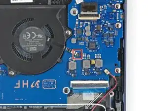
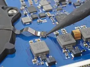
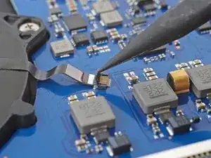
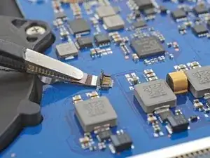
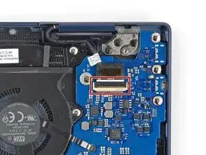
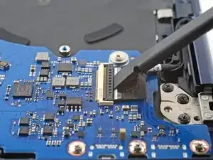
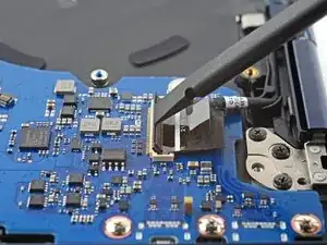
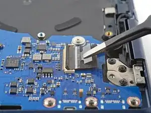
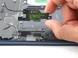
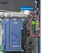
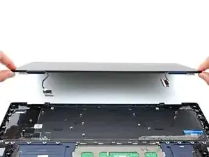
Use this guide to replace the front case on your Galaxy Book Pro 360 15" laptop with a genuine Samsung part.

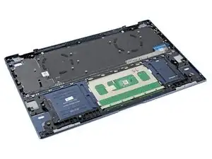
The front case consists of the keyboard and touchpad pre-installed into the frame. Make sure you have the right part before you begin the repair.

Before you begin, refer to the Samsung PC Repair Guide for safety information.

For your safety, discharge the battery below 25% before disassembling your device. This reduces the risk of a thermal event if the battery is accidentally damaged during the repair. If your battery is swollen, take appropriate precautions.

Note: Some photos show the heat sink and primary SSD removed. This is optional, as you don't need to remove the heat sink or the primary SSD to remove the motherboard.

  1. gUKju23eSfPWoTQG
    gUKju23eSfPWoTQG
    fHkm3bbNXXTcaKQo
    • Before you begin, shut down your laptop and unplug it.

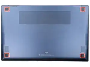
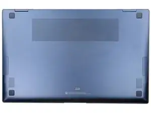
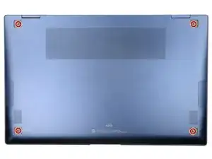
    • Close the screen and lay your laptop down with the rear case facing up to access the four rubber feet.

  2. AjKnV44Yyj2yotFw
    AjKnV44Yyj2yotFw
    oFrIGNcPOxuqMBwH
    4WpNenWhEvrI2KVA
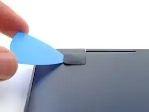
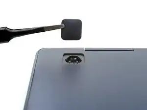
    • Insert an opening pick between the rear case and the rubber foot.

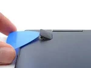
    • Pry up with the pick and dislodge the foot from the rear case.

    • Use tweezers or your fingers to remove the rubber foot.

    • Repeat this process on the remaining rubber feet.

    • There are two types of rubber feet for this laptop. During reassembly, make sure the top feet say "M4" and the bottom feet say "M1".

    • To reinstall a rubber foot, align it over the recess and push down until it's secured.

  3. SfSuoZTK4MfKFZrO
    SfSuoZTK4MfKFZrO
    OdXUvHiCw4S6q6a6
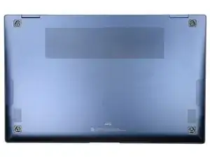
    • Use a Phillips screwdriver to remove the four 4.5 mm screws securing the rear case.

    • Throughout this repair, keep track of each screw and make sure it goes back exactly where it came from.

    • If you're reassembling with the Samsung Self-Repair kit, be sure to replace the screws with new ones labeled #3313.

  4. ULAySQ4d6j2pfZ2J
    ULAySQ4d6j2pfZ2J
    aAhvYQ2LhtPCpdaR
    xFe3aRHgug3abWuN
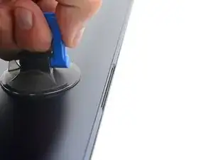
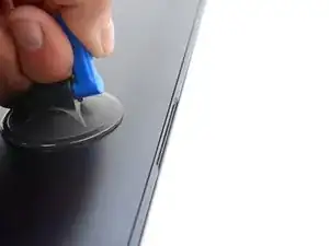
    • Apply a suction handle to the middle of the rear case's bottom edge, as close to the edge as possible.

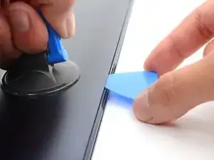
    • Pull up on the handle with a strong, steady force to create a small gap between the rear case and the frame.

    • This may take significant force and multiple tries.

    • Insert an opening pick into the gap you created.

  5. X26VxUYBEWlLnFnT
    X26VxUYBEWlLnFnT
    nuXIk3HwpBNTIJph
    CtglRCBA3QtwfjxD
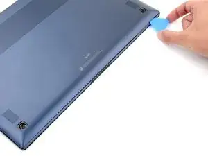
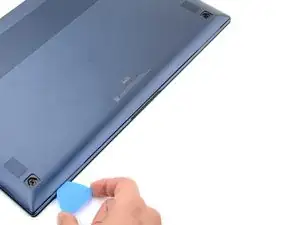
    • Slide the opening pick along the bottom edge to release the clips securing the rear case.

    • Continue sliding the pick along the perimeter of the laptop until all the clips securing the rear case have been released.

  6. FfVedCYiesC1LQjl
    FfVedCYiesC1LQjl
    C5FGqGpdi1KywkvV
    heixK53gSmujF2kK
    • Lift the rear case up and away from the laptop and remove it.

    • During reassembly, this is a good point to power on your laptop and test all functions before sealing it up. Be sure to power your laptop back down before you continue working.

  7. NMC6sQvHpFrTNTMF
    NMC6sQvHpFrTNTMF
    gH1AOpb13HiGR3Mp
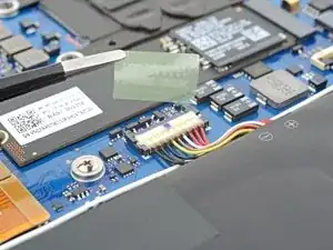
    • Use tweezers or your fingers to peel up and remove the tape covering the battery connector.

    • Set the tape aside. You'll reuse it during reassembly.

  8. APoUcIwRAVkOvStH
    APoUcIwRAVkOvStH
    uVLsPI5oPXUVo3dP
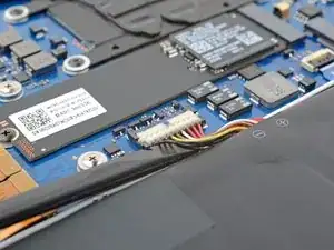
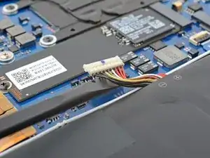
    • Insert the flat end of a spudger under the battery cables, as close to the connector as possible.

    • Gently pry up and disconnect the battery connector from its socket.

  9. 6AaByQhoexBrFXZG
    6AaByQhoexBrFXZG
    FouHLFQ6EArvFJSx
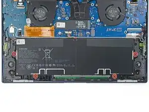
    • Use a Phillips screwdriver to remove the four 4.5 mm screws securing the battery.

    • Take care not to puncture the battery with your screwdriver—a punctured battery may leak dangerous chemicals or cause a fire.

  10. fcwCMowAjoovYYww
    fcwCMowAjoovYYww
    quWAYY3FnVE4QSYq
    swFRqyalI15qAhJd
    • Lift the battery straight out of its recess and remove it.

  11. mILtHZXEI3eOV3Sh
    mILtHZXEI3eOV3Sh
    EwTIjLT3gtSL6lLu
    vD21aLNRZFFB1UuU
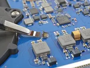
    • Use the pointed end up a spudger to pry up the locking flap on the left fan cable's ZIF connector.

    • During reassembly, make sure that all seven cables are connected to the daughterboard.

  12. yXDv4p6xetX3QNOY
    yXDv4p6xetX3QNOY
    kQFyEAT4EGJR5XHj
    • Grip the left fan cable's pull tab with tweezers and gently pull the cable out of its socket.

  13. XESTAkEkVkrGGWFw
    XESTAkEkVkrGGWFw
    vHJSVsBjBJWR6LBb
    vdnUfAlrFYRpLQve
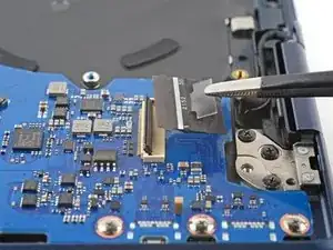
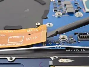
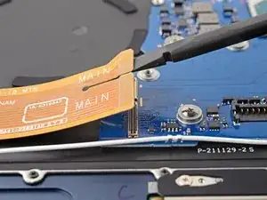
    • Use the flat end of spudger to pry up and disconnect both of the interconnect cable's press connectors from the daughterboard.

    • To re-attach press connectors like these, carefully align and press down on one side until it clicks into place, then repeat on the other side. Don't press down on the middle. If the connector is misaligned, the pins can bend and cause permanent damage.

  14. CnKjVuJlCgOOD2RA
    CnKjVuJlCgOOD2RA
    VXCmlIrAgETRZoEh
    • Use the pointed end of a spudger to pry up and disconnect the bottom left speaker's connector from the daughterboard.

  15. jKxtWwfmECjF2jmQ
    jKxtWwfmECjF2jmQ
    CNiDIALdtmTHXWOI
    tJZklcEUsspFg2mR
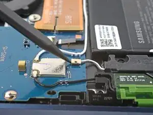
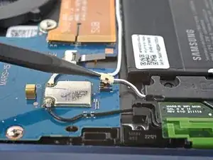
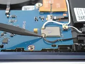
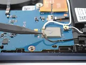
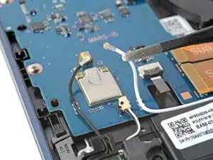
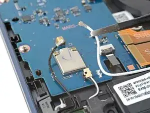
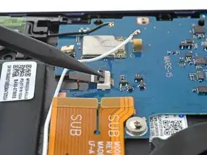
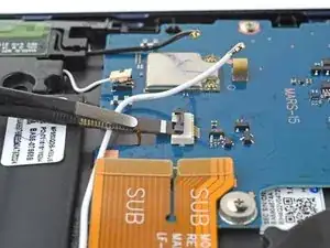
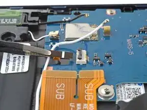
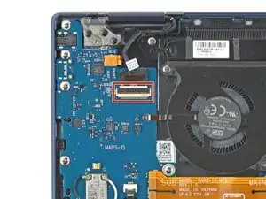
    • Insert the pointed end of a spudger under the black antenna cable and slide it as close to the connector as possible.

    • Gently lift straight up to disconnect the antenna.

    • The connector is very delicate and can easily break if a quick or strong force is applied.

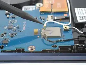
    • Repeat the disconnection procedure on the white antenna cable.

    • To reattach coaxial connectors like these, align the connector over its socket and press down with the flat end of a spudger. The connector should snap into place. This can be tricky and may take a few tries.

  16. UYXkBxXhITFIYsjO
    UYXkBxXhITFIYsjO
    Q2Nij3WPPJdl2as2
    DWVCfmqRTVHox5LK
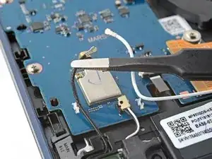
    • Use tweezers or your fingers to lift the black and white antenna cables out of their clips on the daughterboard.

  17. aXx62jh6m4PkhTN1
    aXx62jh6m4PkhTN1
    mksCvyTGmPMPscny
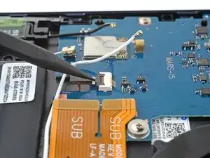
    • Use the pointed end of a spudger to pry up the locking flap on the backlight cable's connector.

  18. mDxrn5ok41c2HKxD
    mDxrn5ok41c2HKxD
    4grcfKr65uiDcXSC
    • Grip the backlight cable's pull tab with tweezers and gently pull the cable out of its socket.

  19. HhmVekFbPUFTRLJf
    HhmVekFbPUFTRLJf
    DfJTC5XiC3UvdxrC
    eDmNM3ht4QImPiCP
    • Use a spudger to pry up the locking flap on the left display cable's ZIF connector.

  20. A14GxFvCI3NDjRSi
    A14GxFvCI3NDjRSi
    MPK3CGVnHRCvMMd4
    • Grip the left display cable's pull tab with tweezers or your fingers and gently pull the cable out of its socket.

  21. fjTtNvELYL3DYd51
    fjTtNvELYL3DYd51
    wxXhrZcFrWk1lHWy
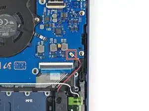
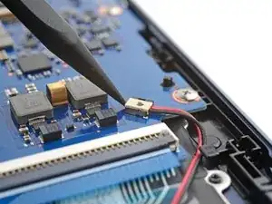
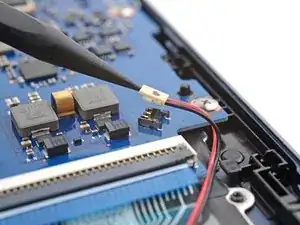
    • Use the pointed end of a spudger to pry up and disconnect the fingerprint sensor's press connector.

  22. NyoBumoZXPZtOHoE
    NyoBumoZXPZtOHoE
    PJLoiADd6ZOGTb6F
    • Use a Phillips screwdriver to remove the five 3.5 mm screws securing the daughterboard.

  23. JBJOwOW3sGE3RAoU
    JBJOwOW3sGE3RAoU
    cBJVyIxrQCdeMXLu
    FevjGxBHFEGFb64e
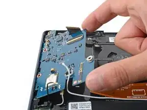
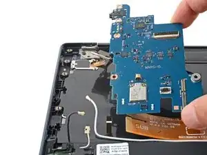
    • Lift the right side of the daughterboard up and pull towards the center of the laptop to remove it.

    • During reassembly:

    • Move all cables that connect to the daughterboard (display, fingerprint, interconnect, speaker, backlight, and antennas) out of the way so they don't get stuck under the daughterboard when it's reinserted.

    • Reinsert the daughterboard at a downward angle to position the headphone jack, USB-C port, and memory slot back into their recesses.

    • Before securing the daughterboard, make sure the alignment pins on the frame are in their cutouts on the daughterboard.

  24. sGdUG5JhUtVlXBw5
    sGdUG5JhUtVlXBw5
    ZHs3fsPbxnsobhSq
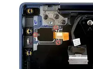
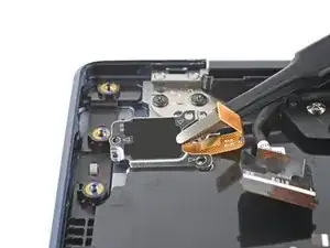
    • Use a Phillips #00 screwdriver to remove the three 2.5 mm screws securing the fingerprint sensor bracket on the top left corner of the laptop.

  25. YMmBtFvUCweKuGQl
    YMmBtFvUCweKuGQl
    hjYqBlVXGTVZ6F4M
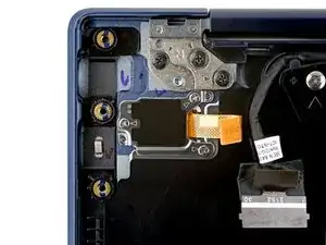
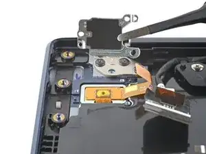
    • Use tweezers or your fingers to remove the fingerprint sensor bracket.

  26. xlhQkqxF1sePmXb2
    xlhQkqxF1sePmXb2
    xhF4jQZ6v41Xsy6D
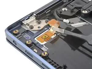
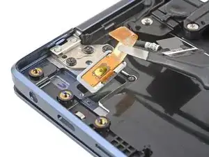
    • Use tweezers or your fingers to remove the fingerprint sensor.

  27. sh1L1kjLaHH6vHvm
    sh1L1kjLaHH6vHvm
    1JuqRfZpYuUKKjAY
    ViMZ2GXhgHPaqgXI
    • Use the pointed end of a spudger to pry up the locking flap on the right fan cable's ZIF connector.

  28. 3TDNY4XIDaEVHEqX
    3TDNY4XIDaEVHEqX
    YabQO2sYV1VBvbxu
    • Grip the right fan cable's pull tab with tweezers and gently pull the cable out of its socket.

  29. cjPLvONN6VwrUkfH
    cjPLvONN6VwrUkfH
    mlBHIDBkeF4phxQR
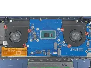
    • Remove the six 3.5 mm screws securing the fans.

    • If you're reassembling with the Samsung Self-Repair kit, be sure to replace the screws with new ones labeled #1650.

  30. ErGmHCYNYwahPD4P
    ErGmHCYNYwahPD4P
    ihGBqUefaRPTxJmR
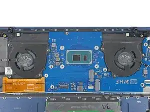
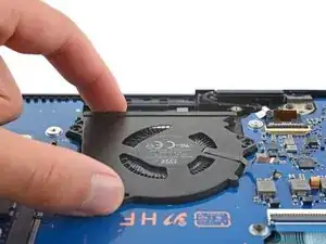
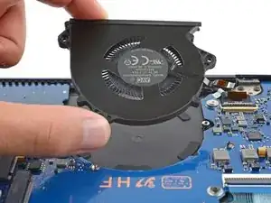
    • Lift both fans straight up and remove them.

  31. ZJEWbTRiahyGQJsH
    ZJEWbTRiahyGQJsH
    i6eoqMtgVFhGmr4n
    hNmxLhNcAkHOcYgX
    • Use the pointed end of a spudger to pry up and disconnect the bottom right speaker's connector from the motherboard.

    • During reassembly, make sure you've connected these five cables to the motherboard.

  32. dlVIoDWLIorWY2bU
    dlVIoDWLIorWY2bU
    LJrBh6LA2ssyKDEP
    • Use the flat end of a spudger to pry up the locking flap on the keyboard cable's ZIF connector.

  33. dcjUKnBjjItsXKe6
    dcjUKnBjjItsXKe6
    3yL3gwsUGeNPNHOn
    • Grip the keyboard cable's pull tab with tweezers or your fingers and gently pull the cable out of its socket.

  34. HHVMs1qlpdswo4TV
    HHVMs1qlpdswo4TV
    x1DdPeFKIseVi5CH
    4GPaAQXfpDFokeK1
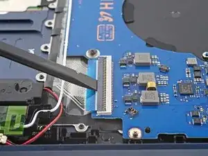
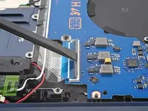
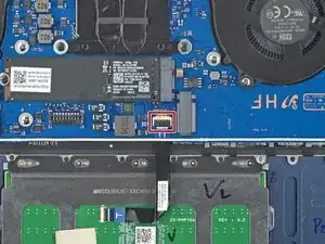
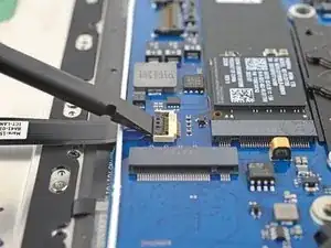
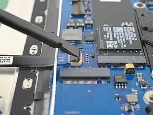
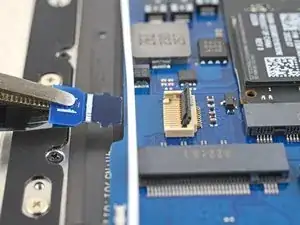
    • Use the flat end of a spudger to pry up the locking flap on the touchpad's ZIF connector on the motherboard.

  35. Jx3cTBCFmF6oqXHK
    Jx3cTBCFmF6oqXHK
    E6XsKGAEr2f5kIHG
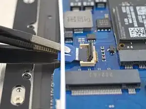
    • Grip the touchpad cable's pull tab with tweezers and gently pull the cable out of its socket on the motherboard.

  36. gTAN56wgQJa5mMkJ
    gTAN56wgQJa5mMkJ
    mb6u4NHL2oTGwxHa
    v6aagko624PFmLTt
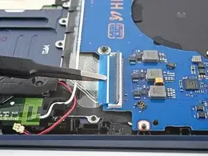
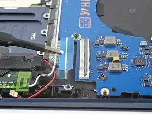
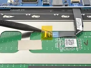
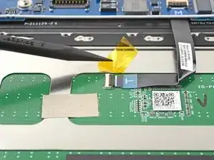
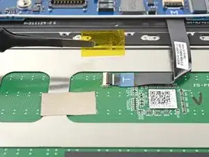
    • Use your fingers or a spudger to peel up the tape covering the ZIF connector on the touchpad.

    • Remove the tape.

    • Set the tape aside. You'll reuse it during reassembly.

  37. TE4YxNZsIBZiWZAb
    TE4YxNZsIBZiWZAb
    dCjhVE1C6LbdoZwg
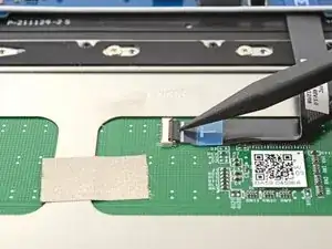
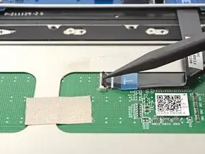
    • Use the pointed end up a spudger to pry up the locking flap on the ZIF connector.

  38. KGSsUQEBkh35KIuE
    KGSsUQEBkh35KIuE
    wn3SMWE3PVPfOobY
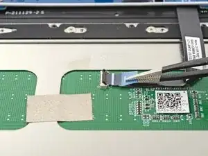
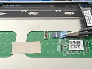
    • Grip the touchpad cable's pull tab with tweezers and gently pull the cable out of its socket on the touchpad.

    • Remove the touchpad cable.

    • Set the cable aside. You'll reuse it during reassembly.

  39. X12GMkojUMXkkDvo
    X12GMkojUMXkkDvo
    NFxuNLqLMEydWOoJ
    aOrhnw6gl2rEnGO2
    • Use the flat end of spudger to pry up the locking flap on the right display cable's ZIF connector.

  40. XQHmWcCYreq52DDQ
    XQHmWcCYreq52DDQ
    WwLP1ecGqiPVqJma
    • Grip the right display cable's pull tab with tweezers or your fingers and gently pull the cable out of its socket.

  41. NUhWxGAIURtwlMG5
    NUhWxGAIURtwlMG5
    Ws4WioQJl3a2polO
    cbAQ2dTGhO1fRyhO
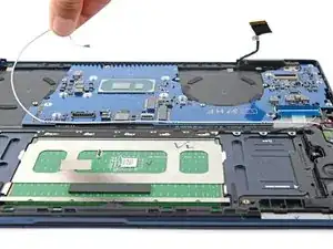
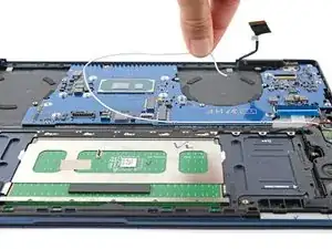
    • Gently pull the white antenna cable out of the three clips securing it to the motherboard.

  42. X1bjE2PM35xYAmra
    X1bjE2PM35xYAmra
    eFf2lYaL1rB4hESj
    qRnZ1yyUoQFsQ6KN
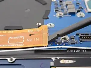
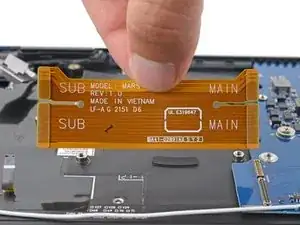
    • Use the flat end of a spudger to pry up and disconnect both of the interconnect cable's press connectors from the motherboard.

  43. sVaBTE1L6wOujCrr
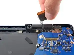
    • Remove the interconnect cable.

    • Set the cable aside. You'll reuse it during reassembly.

  44. OaAOYblYNAqauAmK
    OaAOYblYNAqauAmK
    LHbhOpFvlCstwdhb
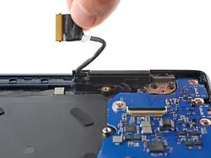
    • Slowly pull the right display cable out of its recess.

    • A small clip secures the cable.

    • Repeat the process on the left display cable.

    • During reassembly, make sure the display cables are secured under their clips.

  45. NnaA25ICRKmar5Em
    NnaA25ICRKmar5Em
    qNJU5ANXqMHjqYY4
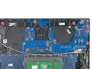
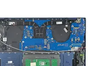
    • Use a Phillips screwdriver to remove the 11 3.5 mm screws securing the motherboard.

  46. EsxyHpbSYIW6Z1nc
    EsxyHpbSYIW6Z1nc
    3AZsiSrQNwN2dDUP
    p6VBNBtOSd6HfF1y
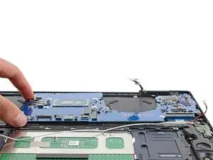
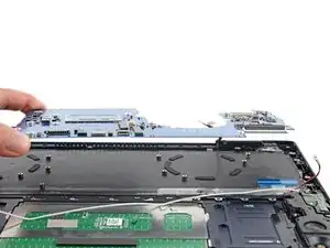
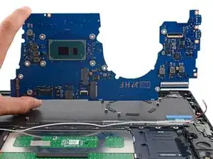
    • Lift the motherboard straight up and remove it.

    • Before securing the motherboard during reassembly:

    • Move all cables that connect to the motherboard (display, keyboard, speaker, and antenna) out of the way so they don't get stuck under the motherboard when it's reinserted.

    • Make sure the alignment pins on the frame are in their cutouts on the motherboard.

    • Push down on right edge of the motherboard to ensure the USB-C and thunderbolt ports are in their recesses.

  47. Lm5uTLPZNYGgmeFu
    Lm5uTLPZNYGgmeFu
    M2Pb6IFCyHn2w6lr
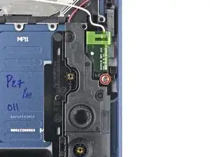
    • Use a Phillips screwdriver to remove the 3.5 mm screw securing the right antenna.

  48. ppDmoL3DXCPJtlMh
    ppDmoL3DXCPJtlMh
    SfyaUVXfJCdE2P4I
    • Use a Phillips screwdriver to remove the 3.5 mm screw securing the left antenna.

  49. Gf1KlIcPiptp1Br1
    Gf1KlIcPiptp1Br1
    ExUMNfGJMDsfOwFH
    wlFjBESL4OAqQlr4
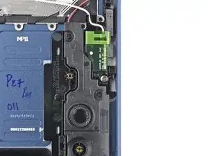
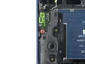
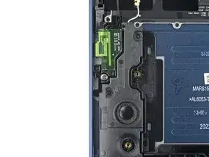
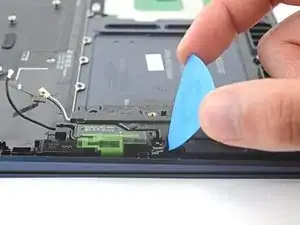
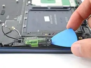
    • Insert a pick between the left antenna and the bottom left speaker.

    • Pry up with the pick to dislodge the antenna.

    • Remove the antenna from its recess.

    • During reassembly, make sure to insert the top of the antennas under their brackets before laying them in their recesses.

  50. UQy2CVuPtgEICDkR
    • Repeat the removal procedure on the right antenna.

  51. QYyW5eisheLny6mu
    QYyW5eisheLny6mu
    CTjdGxvD1eoxQGZH
    WIaSRRDeN2WeP4vR
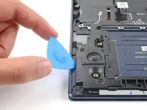
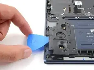
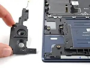
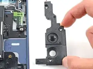
    • Insert an opening pick between the bottom left speaker's left edge and the frame.

    • Pry up with the opening pick to dislodge the speaker from its recess.

    • Remove the speaker.

  52. U1APWqecEfqUWYwy
    • Repeat the removal process on the bottom right speaker.

  53. FJuNCKMIehQGiXCX
    • Open the laptop until it's completely flat and lay it down with the display and keyboard facing down.

    • Before laying the laptop down, make sure you have a clean surface that is clear of items that could damage the display.

  54. jiCEmJ6no4TT1YON
    jiCEmJ6no4TT1YON
    gPmGh3O2SSUTVymS
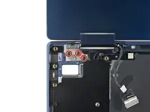
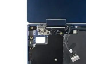
    • Use a Phillips screwdriver to remove the three 3.5 mm screws securing the left screen hinge.

    • During reassembly, install the screws from right to left.

  55. OcobhKP6TcSRPmsB
    OcobhKP6TcSRPmsB
    OU1RQCqrNlwLr3Sw
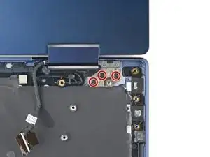
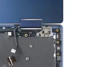
    • Use a Phillips screwdriver to remove the three 3.5 mm screws securing the right screen hinge.

    • During reassembly, install the screws from left to right.

  56. BdAIVm214nB5jpfk
    BdAIVm214nB5jpfk
    eFGAisXkBCKpHtj1
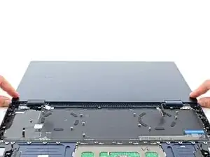
    • Lift the screen away from the laptop and remove it.

  57. 55qgWTGjxuTqiJiR
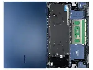
    • You're left with the front case.

Abschluss

To reassemble your device, follow the instructions in reverse order and perform the opposite actions, e.g., "reattach" instead of "removing." Skip steps that use heating and prying, and pay close attention to the 📌 bullets as you work through the steps.

Take your e-waste to an R2 or e-Stewards certified recycler.

Repair didn’t go as planned? Check out our Answers community for troubleshooting help.
Spencer Day

Mitglied seit: 14/09/22

17445 Reputation

0 Kommentare