Einleitung

Replacing the Motherboard is the most complex replacement for the tablet. It utilizes most of the steps from other guides, like battery, front facing, and rear facing camera removals.

  1. JflW6EeJSF5pLUei
    • Before you being the replacement process, make sure the tablet is completely powered off.

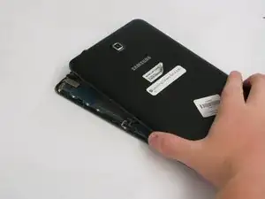
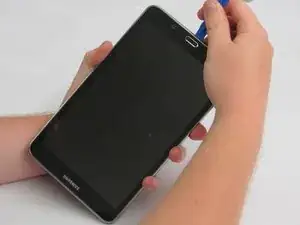
    • Gently insert the plastic opening tool between the metal rim and the back plastic casing at the bottom of the tablet and pry the back casing away from the device. Continue to separate the back panel of the device from the front assembly.

    • Right-handed users will probably be more comfortable prying in a clockwise movement, while left-handed users will feel more comfortable doing a counter clockwise movement.

    • When taking off the rear case there will be periodic clicking noises. Do not worry about those noises. They are just the rear case being disconnected.

    • Be careful not to use too much force as the plastic clips can easily be broken.

  2. PFffRrjThTLgyR3Z
    • Place the tablet screen down on a clean surface.

    • Grasp the back panel and lift it from the device.

  3. Rx24j1KLEIXWM2Aj
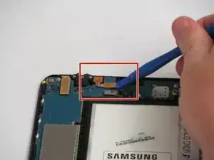
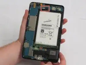
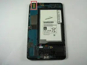
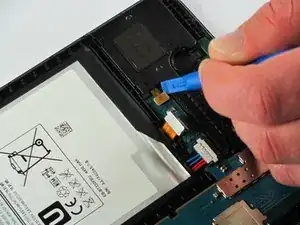
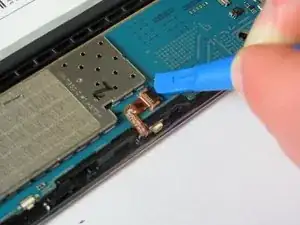
    • The front facing camera's ribbon cable is located at the top edge of the motherboard, slightly left of center.

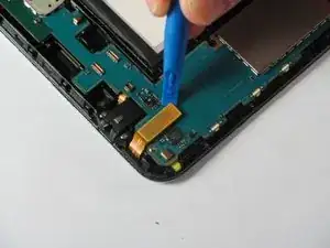
    • Slide the flat end of the blue plastic opening tool underneath the connector at the end of the ribbon cable.

  4. bFkstqZyBaFGbVcg
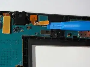
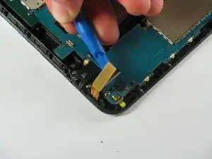
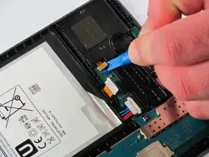
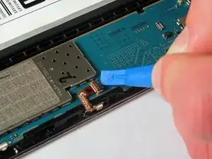
    • Slightly apply pressure and move the blue plastic opening tool downwards to pop the front camera’s gold rectangular connector from its socket on the motherboard.

  5. WotHWRIdxVlYOlJ3
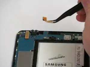
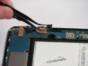
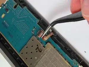
    • Squeeze the gold rectangular piece with the tweezers to gently lift it from its pit.

  6. hVFukVfeYLTDKOXE
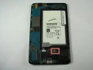
    • The rear facing camera will be located just to the right and below the front facing camera, near the top and center of the motherboard.

  7. 6LP2YYfa5EKNXsVC
    • Slide the flat end of the blue plastic opening tool underneath the rectangular metal connector of the rear facing camera.

    • Apply slight pressure outwards until the camera's metal connector pops from its socket on the motherboard.

  8. WlyfYYr4cOS2dVWA
    • Remove the camera from it's housing with your tweezers.

  9. beieCM6vOKiPaCdQ
    beieCM6vOKiPaCdQ
    luZvSNnlKwmFWfZ4
    NWB1dujoqor2kfjd
    • Slide the opening tool underneath the connector and apply slight pressure upwards and outwards until the metal connector pops from its socket on the motherboard.

    • Device has been rotated 90 degrees counter-clockwise.

  10. dQuLeFxC5DUEBURY
    dQuLeFxC5DUEBURY
    ir1JnRCO41LuxWrI
    j2FPTWUjMsDs3OXH
    • Slide the opening tool underneath the connector and apply slight pressure outwards until the gold connector pops from its socket on the motherboard.

    • Device has been rotated 180 degrees.

  11. PPf6GCvREiLE4DSf
    PPf6GCvREiLE4DSf
    O6Puc5xqXRWktJSB
    BtXSuBcqUD2ECMJO
    • Slide the opening tool underneath the connector and apply slight pressure outwards until the small bronze connector pops from its socket on the motherboard.

    • Device has been rotated 90 degrees counter-clockwise.

  12. KBnHldwpMUl1L6Gp
    KBnHldwpMUl1L6Gp
    bHhjAbQwQDbYCNDo
    YP2K2avJJO3nHO2l
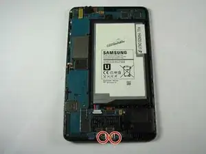
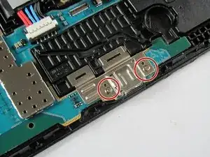
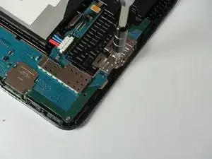
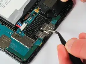
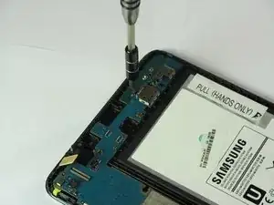
    • Remove both 2 mm #000 Phillips screws from the metal charger port cover.

  13. ZiLIrdJJOpO5absY
    ZiLIrdJJOpO5absY
    Suy2HDBlKhKe4lUy
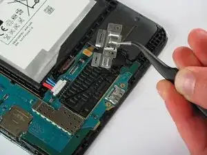
    • Carefully lift the metal cover away with your tweezers.

  14. oCWBVVbWBXDKSWfC
    oCWBVVbWBXDKSWfC
    KqCdspVMA6r1Mx1V
    YflF3MDnoqRnNCXd
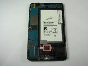
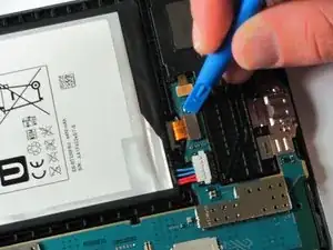
    • Slide the flat end of the opening tool under the black plastic fastener and apply slight pressure outwards until it lifts away.

    • Device has been rotated 90 degrees counter-clockwise.

  15. GLxFyt3PHIuYOtT4
    • Use your tweezers to pull the golden cable out from underneath the black fastener.

    • The cable is fragile, so be careful when removing it.

    • Device has been rotated 90 degrees clockwise.

  16. ScKDBvksVPsXvMJl
    ScKDBvksVPsXvMJl
    XHdTF1laXNKGjrUM
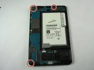
    • Remove all three 2 mm #000 Phillips screws that fasten the mother board to the front panel.

  17. Kp6U2GPKW5HxmiFf
    Kp6U2GPKW5HxmiFf
    BfPdhbtJvVJVdreQ
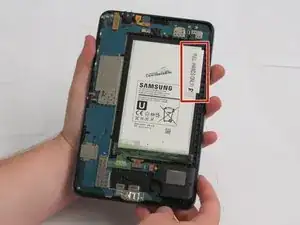
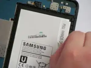
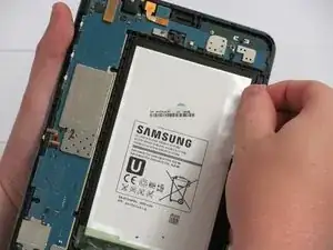
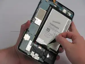
    • Peel the sticker, reading "PULL (HANDS ONLY)," off of the battery starting at the detachable corner.

  18. X2cCYT3skGhQSpDK
    • Grab the top right corner of the battery and pull it out of the device.

    • If there is adhesive keeping the battery in place, use the flat end of the spudger and run it between the battery and the front panel.

    • Do not completely remove the battery as doing so could cause damage to the motherboard and the cables attached to the battery.

  19. wXjKSTsBRpASD5OK
    • Peel away the green tape starting at the bottom left side.

  20. KcGrueeIpKXEyjcQ
    KcGrueeIpKXEyjcQ
    uwxYFXD5JOZN5CiX
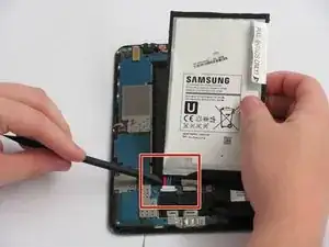
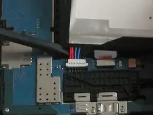
    • Use the spudger to disconnect the battery connector by running it along the underside of the battery.

    • Lift the battery out of the assembly.

  21. cvngG4gcSVw2VxcV
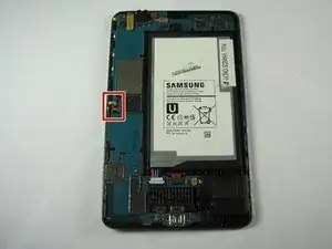
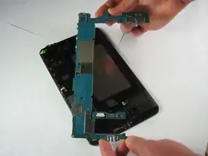
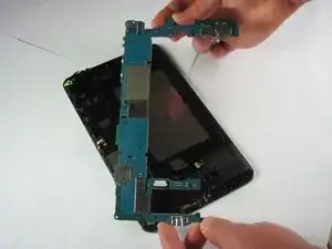
    • Simply grasp the motherboard with both hands from the top and bottom on opposite corners and lift it free of the device.

    • Be sure to place the motherboard on a static-free surface like paper towels so as to prevent any further damage.

Abschluss

Replace the defective motherboard with the new one, then, to reassemble your device, follow the instructions in reverse order.
Jonathan Wharton

Mitglied seit: 12/04/16

299 Reputation

0 Kommentare