Einleitung

Wenn dein Tablet nicht lädt oder nur sehr langsam, dann kann ein Austausch der Ladebuchse abhelfen.

  1. NZ4BLaAsMMLlALPH
    • Wenn du an einem Gerät arbeitete, das noch angeschaltet ist, kann es einen elektrischen Schlag geben. Schalte vor der Reparatur dein Gerät aus und ziehe den Netzstecker.

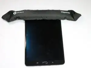
    • Erwärme das Gerät mit einem iFixit iOpener oder einem Heißluftgebläse, damit der Kleber rings um die Ränder des Bildschirms weich wird.

    The whole screen needs to be heated, there is adhesive in the middle as well. The general consensus seems to be that around 80ºC is the temperature to go for, but I found I had to set a heated platform to 85ºC to be able to get the adhesive soft enough, and even then it was not exactly giving up easily.

    CarlW -

    STOP! Read the comments, do a google search. You don’t need to remove the screen to replace the battery. You can just remove the clipped in case back. I wish I would have known this, it is extremely difficult to remove the screen without damaging it (which I did.)

    dmtroyer -

    This is different from yours. The qualcomm version is newer and does not have a removeable back. I’ve tried. You can tell from the later pics in this guide that the back doesn’t come out.

    You’ll notice all the videos online that remove the back are typically not English speakers.

    JM M -

    I have two same Tablet. And both got removeable back. It was very easy open backside and change the accu. PLS Open backside slowly. You have to remove one Flatcable slowly and the backcamera is a problem too. Thx for dmtroyer for the info.:)

    Serdar Bond -

    I have an early-model SM-T715 that was purchased from Amazon in 2015. As dmtroyer indicates, the back comes off. But, it wasn’t easy. To get started, I had to use a suction cup, spudger and opening tool on the middle of the long side between the two round “buttons.” (I couldn’t get any of the corners to budge.) As Serdar Bond mentions, the back camera was hard to pop out. I used a hair dryer to heat up the top of the back cover. This loosened whatever was causing the back camera to “stick” to the back cover. (I don’t think any adhesive was involved.) The flat cable that Serdar Bond mentions is on the left side near the micro SD card tray. I left the flat cable in place and just carefully flipped the back cover around, kind of like opening a book.

    James Kawano -

    Follow-up comments: Some of the tabs on the back cover did not click back into position during reassembly. So, it bulges slightly in two places. This is not an issue as the tablet spends most of its time in an outer cover.

    James Kawano -

  2. 1TBIi3d4HioZQM4C
    1TBIi3d4HioZQM4C
    Bo3dEQh2jnYNgYJB
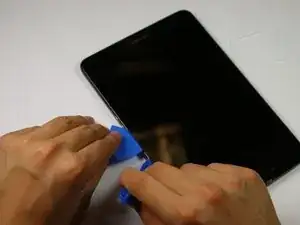
    • Setze das Plastiköffnungswerkzeug in den Spalt zwischen Tablet und Bildschirm an der Stelle ein, von der aus du anfangen möchtest, den Bildschirm zu lösen.

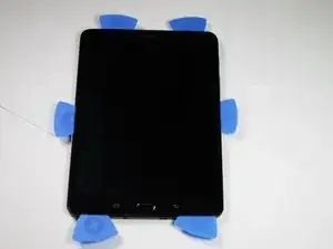
    • Setze ein Plektrum in den eben geöffneten Spalt zwischen Bildschirm und Tablet ein.

    • Wiederhole rings um das ganze Gerät, bis oben und unten je zwei Plektren stecken, an den beiden Seiten je eines.

    There is no warning about how close the LCD cable is to where you are instructing to insert the pick. Also No warning about menu/back buttons.

    universalelectronicsbc -

    This won’t work. There is no way that a guitar pick is going to go in between the bezel and the glass and lift it up. You need to attach a sucker to the glass around the middle of a long side (ideally the righthand side) and pull it, when the whole screen is hot enough to soften the glue. That will open a gap big enough to get a pick in. Picks alone will not free the screen, because they are not long enough, and if you are careless around the bottom (or even if not) chances are you will at the very least disturb the ribbon with the home buttons etc. See the pic in Step 5 (which does not match its caption, but shows the main board removed - if you look at the front of the main board, you can see that the right-hand touch button sensor has been damaged and pushed up out of place. This is not necessarily a major issue - a replacement button ribbon is not that expensive - but it’s worth knowing about.

    CarlW -

    Do not try to lift all round the screen with picks like this, it will break. Although it is fragile, it will bend a certain amount, and the digitiser glass is actually pretty tough, but the LCD beneath is delicate, glued down, and also surprisingly expensive - the screens on these are super high res, an unusual aspect ratio, and cost a fortune compared with typical tablet screens. If you have the t713 model, and break the screen, you can fit the LCD from, I think, any of the other models in the series; they are the same resolution and spec but for some reason a different part number, and the “official” one for the T713 is at least 50% more expensive than the others (which are still pricey.) (I know for a fact that the T710 screen works on the 713 because I broke mine, and took a chance on the cheaper screen.)

    CarlW -

    Once you have an opening on one side, study the pictures of the innards, and of replacement screens on ebay, and note where the glue is and where the button and screen ribbons are. You will need to use something like thin plastic card (obviously something that doesn’t soften at 80ºC) to slice through the glue all the way under the screen, being careful not to damage the screen ribbon in particular. This will take a lot of time and patience, and you will need to keep the whole screen up to 80ºC or so (probably OK up to 90ºC) while you’re doing it. You can move the sucker around as you lift it gradually, but be aware that if you lift too far, the digitiser will come up and separate partially from the LCD, which will still be stuck down in the middle somewhere, and the LCD will crack and it’s game over for that screen - you’ll be very lucky to replace it for under £100 UK.

    CarlW -

  3. fV6ZxIRWIPA22prk
    fV6ZxIRWIPA22prk
    UhxuwNFB1HSbFOjx
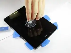
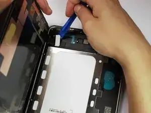
    • Entferne den Saugheber vorsichtig aus der Ecke, ohne den Bildschirm zu bewegen.

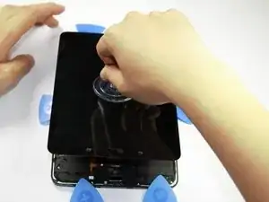
    • Setze den kleinen Saugheber in der Mitte der Scheibe an, hebe hoch und löse die Scheibe.

    • Der Bildschirm ist immer noch mit dem Rest des Gerätes durch ein Kabel verbunden, ziehe also nicht zu schnell hoch.

    No warning about the adhesive covering the middle of the LCD holding it down, this will cause the LCD to crack when removing as instructed by this method unless that is completely cleared first, and this is not possible using picks that go in 1 inch.

    universalelectronicsbc -

    Seconded the above comment. You need to slide thin, heat-stable plastic card under the screen from the edges in, slicing through the glue, paying particular attention to where it’s glued down in the middle/left, near the ribbon. You will very likely damage the home/back button sensors and ribbon, this probably can’t be helped and that part is cheap to replace. You will also damage the lightproof rubber gasket around the front camera, again, can’t be helped. The important thing is not to break the LCD or its ribbon. The plastic cover shown in the next stage with the caption about disconnecting the ribbon will stop your slicing card from damaging the ribbon connector, and there’s no glue on that or immediately to the right of the ribbon. But there is glue on the metal frame beneath the ribbon, and it’s very tenacious glue. There’s another patch of it on the righthand side of the metal frame, which is shorter. The strip on the left is nearly the whole length of the metal bit.

    CarlW -

    So with reference to the second picture here, you need to slice under the screen from the left with a stiff card, starting from about where the person’s left thumb is, and right down to the bottom, going under the screen about 3cm, to just short of a line extending up the screen from the lefthand lower touch button, where the leftmost pick is positioned in the picture. From the right, you need to slice in about halfway across the screen,all the way down to just before the righthand lower touch button. And you need to slice in about 2cm top and bottom, and 1cm for the upper left side and the lower right side (the bits you didn’t slice further under for). Only when you are convinced that the only thing still holding the screen on is the ribbon should you attempt to lift it more than a millimetre on any edge. As I said above, it will bend a bit, but lift any more while the glue on the metal frame is still attached and the LCD, which is much thinner than the digitiser glass, will shatter.

    CarlW -

  4. jXZMKjVSbmQSCIuY
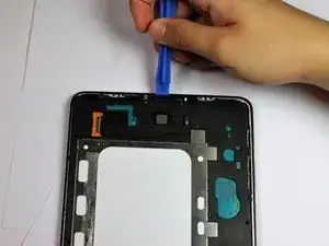
    • Setze das Plastiköffnungswerkzeug unter das Flachbandkabel, welches den Bildschirm mit dem Tablet verbindet.

    • Hebe das Werkzeug vorsichtig an, um das Flachbandkabel vom Tablet zu lösen.

    • Entlade jegliche statische Elektrizität, indem du ein geerdetes Metallobjekt anfasst, bevor du ins Innere des Gerätes greifst.

    Where is the cable? Top left corner or bottom right corner?

    Joon Hansen -

    The ribbon cable is in the top left corner of the tablet, and folded - there’s no glue on the ribbon itself, but there is glue along the edge beside it, and glue along both sides of the metal frame you can see here - that glue is attached directly to the delicate LCD part of the display, which will shatter if you try to lift the display assembly while that glue is still attached. There is no glue on the exposed part of the face of the battery (white bit). There’s a thin strip of glue down the length of each long edge, but no glue between those strips and the metal frame - you can see where the glue is, in fact, on the above photo. The top and bottom edges have a wider strip of glue than the sides do. The thing being prised out in the picture is a plastic cover, not the connector itself. It’s wedged in quite tightly and needs to bend somewhat before it’ll pop out exposing the connector, which can then just be delicately separated with a spudger by lifting it up.

    CarlW -

  5. t2DJChHExcoCvX1J
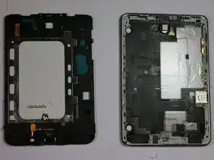
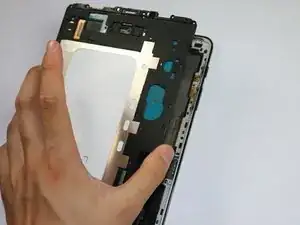
    • Nun ist der Bildschirm vom Rest des Gerätes frei.

    Wrong picture?

    This picture seems to be the result of step 6.

    Rini van Zagten -

    This doesn’t show the screen, it shows the mainboard removed, though the small metal cage about 1/3 up from the bottom right, and the camera, should be attached to the main board (leftmost in the picture) and not left behind on the frame. If you look carefully at the main board shown here, which is viewed from the top side (i.e. the side the screen was glued to), you can see the touch button sensor has been torn away and pushed up on top of the battery (middle of the lower edge of the flat metal battery frame) The sensor is meant to be down beside the home button, like the one on the left. It’s really hard not to do this while separating the screen glue, but don’t panic if you do because the ribbon assembly is detachable and fairly cheap (a few pounds UK).

    CarlW -

  6. hwQfmBMkWxRGYDNO
    hwQfmBMkWxRGYDNO
    ZO1WJbIoPpssJvCG
    FjBN1bvsuBxE2GHN
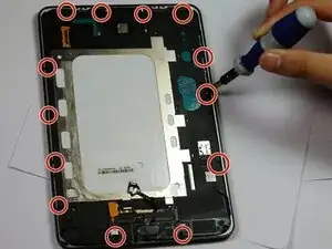
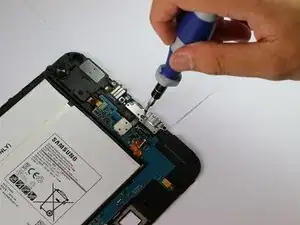
    • Entferne die dreizehn 3 mm Kreuzschlitzschrauben #1 rings um die Kanten.

    • Hebe die Abdeckung der Hauptplatine vorsichtig hoch und entferne sie.

    There are fifteen screws, almost where shown, but not quite - most are around the edges and pretty obvious, two hold the spring-loaded recessed button things (for a dock I suppose) and there’s one next to the camera. To lift the main board out, once you’ve removed the 15 screws, it will seem like it’s still stuck top and bottom. There are tabs at the top, and the connectors hold it at the bottom. Press in the springloaded dock recess button thing from behind to lift the top lefthand corner of the main board enough to get a pick under, and just wedge it like that or get a fingernail under it. Then take a chisel type craft knife blade or something equally thin and strong (I was unable to do this with a plastic spudger) gently lever the top edge of the plastic away from the edge and pop the tabs free. Refer to the picture in stage 5 to see the tabs on the top edge.

    CarlW -

    Once the top edge is free, the board will lift away at the top, but still be stuck at the bottom - again, lever it a bit with something thin. The bit that will hang on is the 3.5mm headphone jack - it sort of clips into the frame a bit - be gentle and patient, you don’t want to bend the mainboard.

    CarlW -

  7. xDYKAWMBdWZsFICo
    xDYKAWMBdWZsFICo
    kdTFZxXGOcyx6WUR
    2QGmIsFbSGBWHZLX
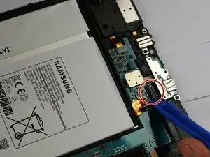
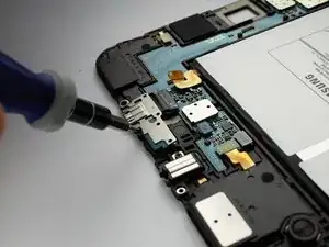
    • Löse die Ladebuchse mit einem Schraubendreher von der Hauptplatine.

    • Löse das Flachbandkabel der Ladebuchse mit einem Plastiköffnungswerkzeug von der Hauptplatine.

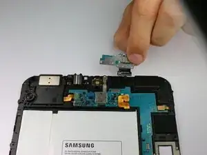
    • Entferne die Ladebuchse vorsichtig von der Hauptplatine.

    Some of the charging boards for these have a microphone on a ribbon as well, presumably for the versions that also function as a cell phone. Check which sort you need. In picture 1 here you can see the kind of plastic “claws” on the 3.5mm headphone socket that clip the bottom of the board to the frame.

    CarlW -

Abschluss

Um dein Gerät wieder zusammenzusetzen, folge den Schritten in umgekehrter Reihenfolge.

Jonathan Wood

Mitglied seit: 19/04/17

996 Reputation

3 Kommentare

My tab s2 is not charging. Changes charging port & battery still not charging. the part just below battery is getting very hot. what maybe the solution.

Ganesh D -

For nubes (like myself) it would have been helpful to mention that there is no adhesive on the sides of the screen but if there is, it will be much thinner than the top or bottom of the device. This is why you need to use the suction cup to pull open one side of the screen in the middle just enough to insert a pick. You can work from there by heating the top or bottom and working an opening tool slowly around both ends. Needless to say the glass on the screen is very thin and fragile, take your time and don’t expect to get this done in 20 min., it can take much longer if you have to repeatedly heat the area you’re working on with the opening tool to release the adhesive. A heat gun is much better for this purpose than the iOpener.

Hieronymus Bosch -

Really terrible guide, no warning about the danger of damaging the menu or back button, no warning about how close the LCD cable is to where the insctructions are telling you to insert a pick and damage it. No warning about the fact that the LCD is adhered to the miframe all over, in the center etc. So following these instructions will crack your LCD. Unless you heat it to the point the LCD will be damaged from heat anyways……Really missing a lot of critical information on this guide and just cost me 210$ thanks.
universalelectronicsbc -