Einleitung

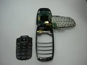
Use this guide to remove the logic board assembly from the casing.

  1. t5g453sjnObDMqDH
    • Turn the cell phone so that the back side is facing you.

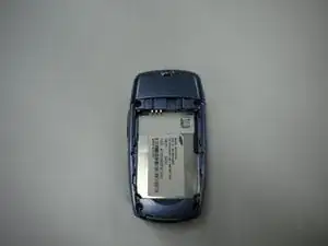
    • Press the upper indent and slide the back cover down.

  2. AtTEKYqhIS5xZNuE
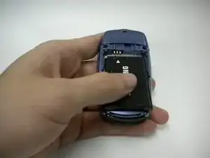
    • Pull the battery up from indent at the bottom and slide it out.

  3. BZRRxVCZGS5ZmZd1
    • Set the battery aside.

  4. uxgtYJYT2BZGGIIZ
    • The outer casing consists of two separate parts on the upper and lower halves of the device. The upper outer casing is held on through a combination of screws and tabs.

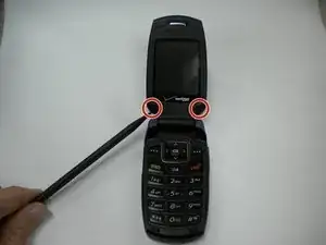
    • First, remove the plastic plugs covering the screws with a spudger.

  5. NRZPCgfcWuCrDUei
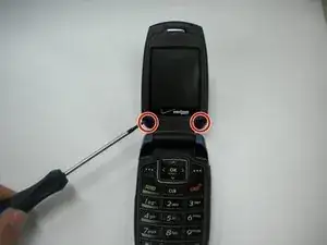
    • Underneath the plugs are two small screws that can be removed with a small Phillips screwdriver.

    • The screws will need to be pried out after unscrewing them due to their size.

    • Take care not to lose the screws as they are small and have a tendency to roll.

  6. xcMLQXQSEisGWPf1
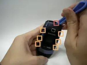
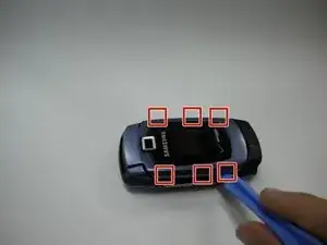
    • The outer cover is now secured with seven tabs: one large tab (marked in red) and seven smaller tabs (marked in orange).

    • To begin removing the outer cover, start by prying the large tab up with a flat object.

    • See next slide for details for smaller tabs.

  7. qFfRS4YlGZu2YhtX
    • Continue to pry each smaller tab up, taking care not to break the tabs.

    • If disaster strikes and a tab is broken, the outer casing can still be put back on assuming the majority of the tabs are still intact.

  8. ROeyMCTNxwY6xJEN
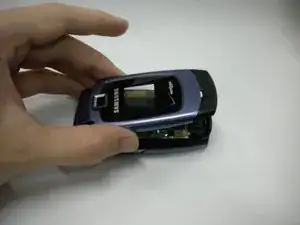
    • After the last tab is removed, tug gently on the outer casing to remove it.

    • Don't pull too hard, or you may damage the wires connected to the speaker.

  9. jEXOlplHtKSBbyQn
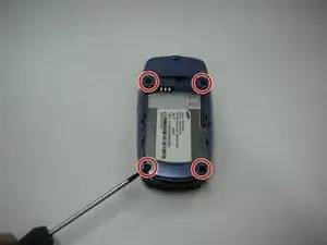
    • The lower casing is held on by four screws in the corner of the battery enclosure. Remove these screws.

  10. 6MXarvdBtlpoT2JT
    6MXarvdBtlpoT2JT
    V2wFO4JrDO4oDsNd
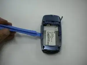
    • Use a spudger to pry the back assembly off of the device.

  11. MuRIK41KKJRfFFN1
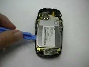
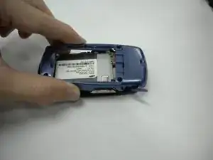
    • Use spudger to pry logic board from the casing.

  12. gBpNngBQT54JE6bF
    • Rotate the logic board assembly out of the casing, being careful not to break VGA cable.

  13. KoINZbHY1WlcAAag
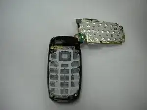
    • Lift the number pad straight up from the casing.

  14. Ltf1nSvdNiPtH3sg
    • Set the number pad to the side.

Mitchell Walker

Mitglied seit: 21/01/10

25 Reputation

0 Kommentare