Einleitung

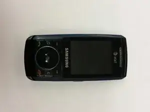
This guide will show you how to access and replace the circuit board in the phone's body, which contains both the screen and camera.

  1. syMTk4iMbYnDBKLf
    syMTk4iMbYnDBKLf
    grRkeHDUpAnxvJRp
    • Gather all the materials required prior to the teardown.

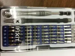
    • A Phillips PH000 screw head and screwdriver are the only required tools for this guide.

    • Make sure to use the correct screwdriver head in order to avoid damaging screw heads.

    • Avoid over tightening the screws to avoid damaging them.

  2. d2vbmP4fNJiPErTM
    d2vbmP4fNJiPErTM
    JRJkCEkjElBtxXPW
    nvWWHFsWUDIPqAIW
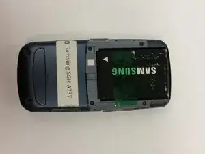
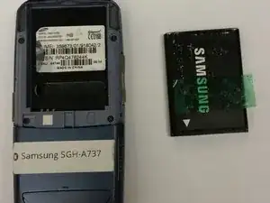
    • Remove the battery from the back of the device.

  3. vfOTiWImcrVGoJGx
    vfOTiWImcrVGoJGx
    SeyIEHTeerFHXvhi
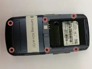
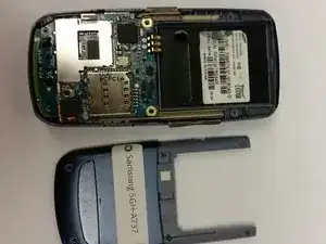
    • Using the screwdriver, unscrew the six visible screw drivers on the back of the phone.

  4. s1DRATq4fEwaQhmi
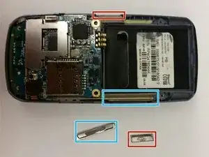
    • Remove the silver side buttons and set them aside.

  5. SHhCq4mtDgpOutR6
    SHhCq4mtDgpOutR6
    LgA1Um4YVrCZrBwN
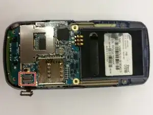
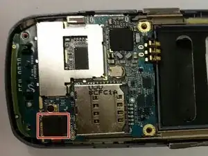
    • Gently lift up the connector at the bottom left of the phone as shown in the picture.

  6. cFlpRvxOGLjXFdEi
    cFlpRvxOGLjXFdEi
    6OAF2cAEEwOwyMik
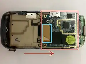
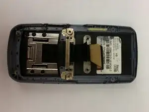
    • Flip the circuit board up to unveil an orange connector near bottom of it.

    • Gently unplug the connector by prying on the corner with a finger.

  7. dEtSNKWm6mI3lcaQ
    dEtSNKWm6mI3lcaQ
    PKMcYkICT1cJr51o
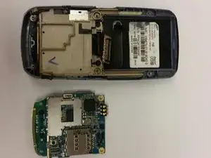
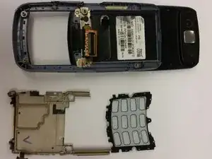
    • Lift up the tan circuit board holder to separate it from the device.

  8. UKRYaV4FAwMLQLFo
    UKRYaV4FAwMLQLFo
    ha4sE1GfUBpPMOSq
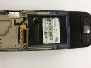
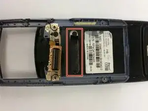
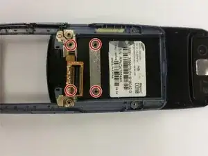
    • Peel off the black strip below the product sticker, unveiling two screws and unscrew them.

    • There are two more screws a little bit below them that need to be unscrewed as well.

  9. bTXQ6XqOyrLZLWtn
    bTXQ6XqOyrLZLWtn
    PyBZHY5t3RaG6ntx
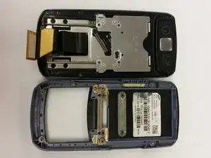
    • Make sure the phone is closed. If not slide it closed now.

    • Separate the blue plastic panel from the phone which should already be trying to come off.

    • Slide the connector gently through the rectangle gap in order to avoid damage.

  10. ZugVhy3cPp5Sv4PV
    ZugVhy3cPp5Sv4PV
    GfNpyS5M6TUjvQDk
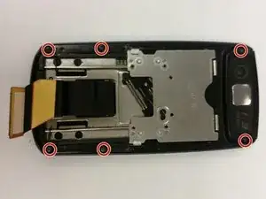
    • Remove the six visible screws from the outer edge of the device.

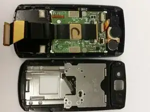
    • Separate the panel unveiling the circuits and camera.

  11. KGqOdVxoEFplPNXI
    KGqOdVxoEFplPNXI
    LLRpQsFdAsPFZsMq
    sOO4gTQtfYIptrSo
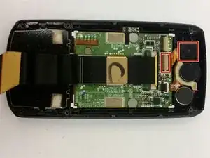
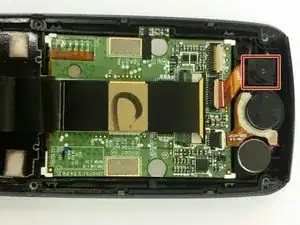
    • At the top right is the camera according to the image.

    • Gently lift up the tan flap away from the camera (where the orange connector goes to) which should disconnect the wire.

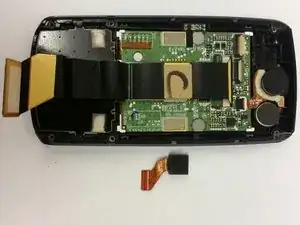
    • Pry up on the camera to dislodge it. (May take a bit of force)

    • Replace the faulty camera with a new one.

Abschluss

To reassemble your device, follow these instructions in reverse order.
Tommy

Mitglied seit: 19/02/16

101 Reputation

0 Kommentare