Einleitung

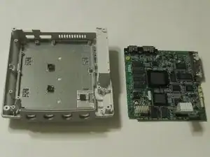
A guide to remove the Logic Board from the Sega Dreamcast.

  1. rdFJlNVwMtT3hJRD
    rdFJlNVwMtT3hJRD
    BGojrPldMPBm4Yew
    • Verify that the console is disconnected from the AC outlet before you begin.

    • Flip the console over on its back.

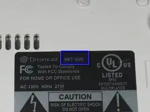
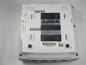
    • Take note of your model number, in case replacement parts are needed.

  2. HDbDfaw3TOGBMCHi
    HDbDfaw3TOGBMCHi
    b12VKhkOV53BrRt3
    ZxvUK2uvuTY4pH1H
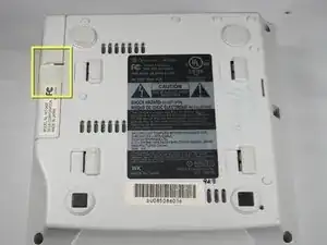
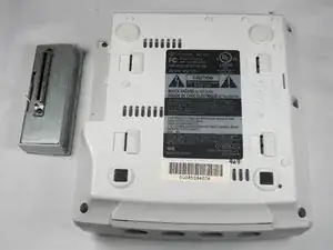
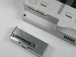
    • Remove the expansion bay by applying pressure to the small clip on the expansion bay while prying it away from the console.

  3. j4mn2GW3UHoTNIAH
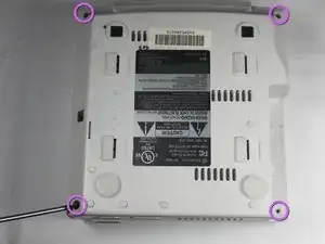
    • Locate and remove all four black 12mm Phillips #02 screws from the underside of the console.

    • Note: Remove the expansion bay to locate the fourth screw

  4. KGQFrciudkmBDQJX
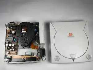
    • Internal components can be loose. Be careful that they do not fall out when removing the cover.

    • Turn the console right side up.

    • Remove the top cover by gently lifting the upper portion of the console.

  5. jyBUYSfshPqZkPFi
    jyBUYSfshPqZkPFi
    CFapUZAT5FMHNsIG
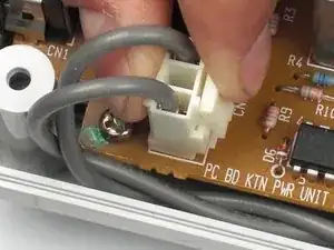
    • Verify that the console is disconnected from the AC outlet before you begin. If you have just powered off the system, give the capacitors a few minutes to discharge before you begin working.

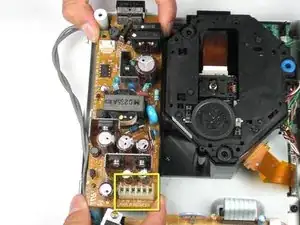
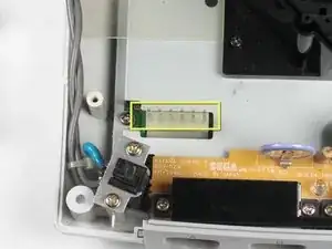
    • Remove the white female pin header by clamping the clip and pulling it up gently from the power board.

  6. VNFffdBYp2eUXyHN
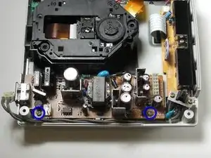
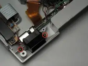
    • Remove the two 10mm Philips #02 screws that are fastened to the power block.

  7. XgMCYlIimpObCCZU
    XgMCYlIimpObCCZU
    OaYoOp12FpdttLGO
    • Do not bend the male pin header between the mounted head when you remove the power supply from the chassis.

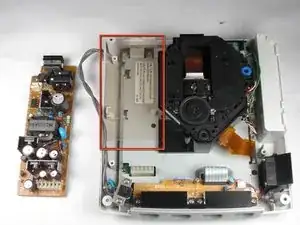
    • Remove the power board by using both hands to gently lift the power board away from the console.

  8. l3TNMLFWvv3Yd6i5
    • Remove the clear plastic film that is tucked between the power supply and the chassis.

  9. sTkunRJrnS2ghCtU
    sTkunRJrnS2ghCtU
    spGdacnu5ME4BPv2
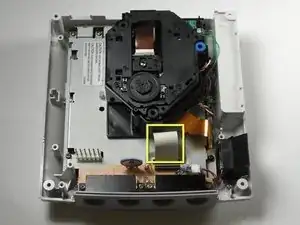
    • Be gentle with the white controller cable as it can be a bit fragile.

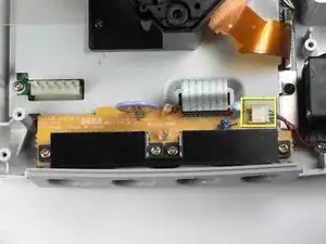
    • Disconnect the white controller cable by gently pulling the the cable while wiggling it back and forth until it detaches from the controller board.

  10. arRQupUNRImkrXRS
    arRQupUNRImkrXRS
    dKVv1VCXn1jmFMCf
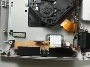
    • Remove the four 14mm Philips #02 screws located on the controller board.

  11. ZODCHfjIJ1WlPSjb
    ZODCHfjIJ1WlPSjb
    LPN1ltPGsaAZNGWt
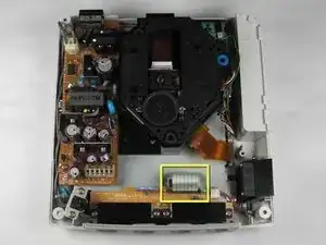
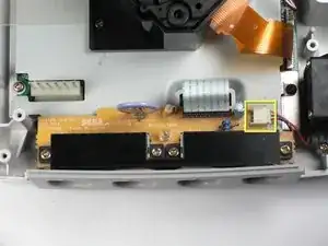
    • Disconnect the white fan header from the controller port.

    Perhaps list the battery type an battery holders that allow for easy replacement in the future?

    Brett Kampf -

  12. 35Bjo2fcSKkqAqSa
    35Bjo2fcSKkqAqSa
    LiVmAEBfYsNHGqwC
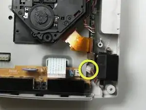
    • Remove the controller board by lifting it up from the controller port.

  13. UqnkwsEhKXEaDccZ
    UqnkwsEhKXEaDccZ
    WCnVuvsLWJUYqnId
    • Detach the orange cable by giving it a gentle pull while wiggling the cable back and forth until it loosens from the logic board.

  14. ms2ncVxe2h4NQsNb
    ms2ncVxe2h4NQsNb
    TUZoEl54cKfFU6EM
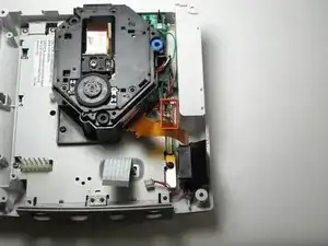
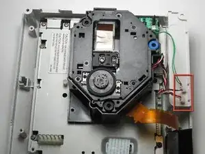
    • Detach the cables by gently pulling the three GD-ROM cables to remove them from the logic board.

  15. P6mDmXfpjHs3QMpt
    P6mDmXfpjHs3QMpt
    noSoOLAmlYwJyxMN
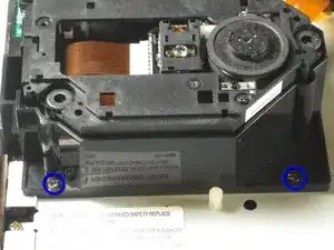
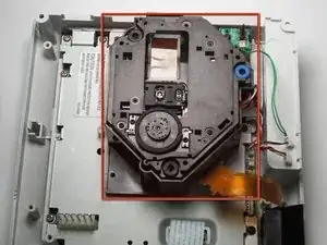
    • Remove the two black 12mm Philips #02 screws located on the left side of the GD-ROM bracket.

    • The console is rotated 90 degrees counter-clockwise in the first photo. The second photo depicts the normal position.

  16. S65eQ5lEBJeGT5aj
    S65eQ5lEBJeGT5aj
    rFmcoWxRScGUCISp
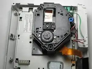
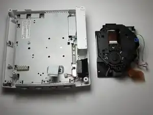
    • When lifting the GD-ROM, be careful that the top half of the casing does not detached from its base.

    • Remove the GD-ROM by gently lifting it from its base.

  17. 1wIiMZDBQZFPTkcv
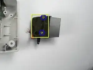
    • Remove the white fan header by gently pulling it away from from the controller port.

    • The white fan header may already be detached if you have completed the Controller Port Disassembly Guide.

  18. rAFBm1RFSarPyiKA
    • Remove the two 8.5mm Philips #00 screws from the fan bracket.

  19. 55CdJtvg1vQvIGFS
    55CdJtvg1vQvIGFS
    yRF1Wp3LH3JLrCCL
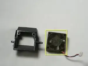
    • Remove the two 17.5mm Philips #00 screws from the fan bracket.

    • Remove the fan from the bracket.

  20. hwg2nPTW3CYdOXsT
    hwg2nPTW3CYdOXsT
    bKrKp5BgWvnyu3Gd
    d1Jy41rOAtIj6mVN
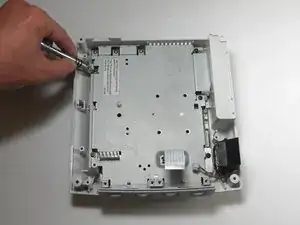
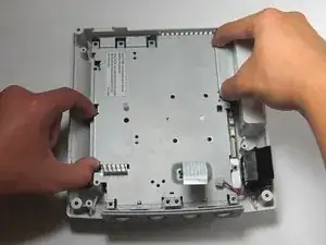
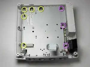
    • Remove the five 10mm Philips #02 screws from left side of the logic board cover.

    • Remove the three black 12mm Philips #02 screws from the right side of the logic board cover.

  21. hnhU6WKGFT5I4YSM
    hnhU6WKGFT5I4YSM
    TcTKkJE34PTkFxqH
    iEpXeKTAmdIZRVBT
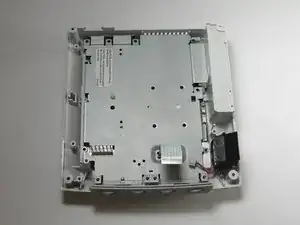
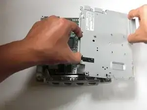
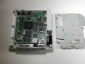
    • Lift the metal cover from the console.

  22. ahtsoP1WeNBoMAsu
    ahtsoP1WeNBoMAsu
    WfYjUylJZ6N64Oay
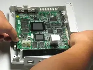
    • Before handing the logic board, you may want to use a grounding strap to protect the device from static charge. If you do not have a grounding strip, you may ground yourself by touching a large metallic object.

    • Remove the logic board and set the logic board on an anti-static surface.

Abschluss

To reassemble your device, follow these instructions in reverse order.

wkwong

Mitglied seit: 14/11/09

468 Reputation

Ein Kommentar

helpful but my dreamcast had a different logic board and as well as fan and gd-rom so keep that in mind if u see something different in your unit
Nickolas Wilcox -