Einleitung

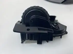
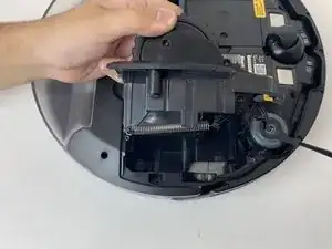
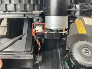
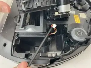
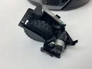
The drive motor/wheel assemblies are a vital component to the R75.

the assembly includes:

  • a drive motor
  • a small gear system
  • a drive wheel
  • a motor controller
  • the R75’s suspension system

Each of these components can be replaced individually, however, you will rarely find a single component being sold as a replacement, whereas the complete assembly can be ordered.

You may want to remove the drive assembly in order to replace a failed drive motor or to clean out hair or debris from the drive wheel. If a drive motor has failed, you should notice your robot’s ability to move become severely impaired, if not fail entirely.

It is important to occasionally inspect the wheels for any sort of wear and debris build up.

  1. yd1jGlpLTDRc1hHf
    yd1jGlpLTDRc1hHf
    XNNtWHGMoY5GxiE5
    FEsGvqsPYxCsancT
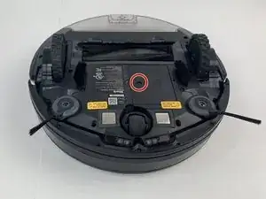
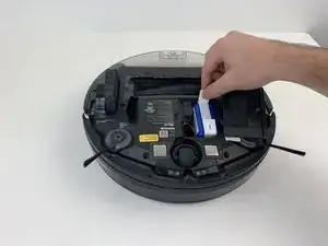
    • Make sure the robot is shut off by pressing the power button on top.

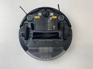
    • Flip the R75 over so that the underside is facing up.

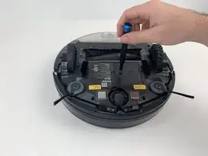
    • Using a Phillips #1 screwdriver, remove the 4mm screw in the battery cover.

    • Remove the battery cover.

    Here, you have misused the reminder bullet. The note bullet would be better in this case; I would also say how to turn it off, rather than just to do it. Avoid locate steps, and instead, move straight to the information about what to do. Use markup on the images to indicate where the component is. Be careful about using “remove” without other information about how to remove it, especially if there are multiple ways to remove something.

    Alex Watkins -

  2. eNek1rNlHGuxOQoA
    eNek1rNlHGuxOQoA
    guxEldPlLS5pacye
    GLpTIqMocSKtTEpG
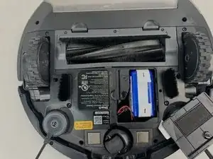
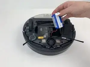
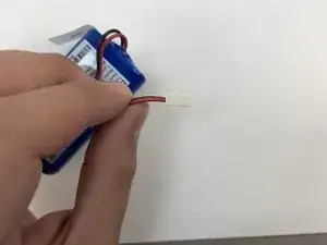
    • Be careful when removing the battery, as it will still be connected to a wire.

    • Slowly pull the white tabs outward to remove the battery.

    Make sure to review how to appropriately use special bullets. Make sure to check throughout to remove “locate” steps, and instead, just go straight to the action.

    Alex Watkins -

  3. CqrfN2ORRlhjOLfR
    CqrfN2ORRlhjOLfR
    TDLOlROYnNnNHnAK
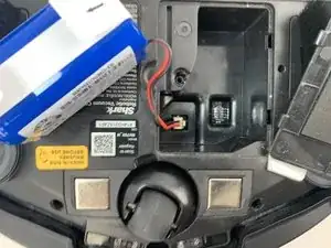
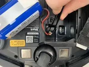
    • Be careful when removing the connector, as the part can break if too much force is used.

    • Push down on the tab of the battery connector using a set of tweezers and pull the connector away from the robot to free the wire.

    • Remove the battery from the device.

    Here, you’re using tweezers, but you don’t indicate that in the guide steps. Instead of including the information in the special bullet, I would just integrate the tool into the actual procedure. Do you have pictures of you pushing the tab? Can they yank the wire, or do they need to pull gently? I would add a flipbook style action shot to make the procedure clearer in the pictures.

    Alex Watkins -

  4. VtUDoejRD3vsoG6p
    • Flip the R75 to its underside.

    • Make sure the R75 is shut off.

    • For extra security, disconnect the battery by following the prerequisite guide.

    Here, the device was already oriented this way, so the directions on the side sensor with using this prerequisite make the procedure confusing. Make sure to read through all guides to make sure you don’t have these kinds of continuity errors. Also, include the battery replacement as a prerequisite for all guides, and use the system to include the prerequisites, rather than putting this information in the note.

    Alex Watkins -

  5. a22HkVXVdlQa5df1
    a22HkVXVdlQa5df1
    QqSNPmhse16yECIP
    kNHbFBibAC6q2QTO
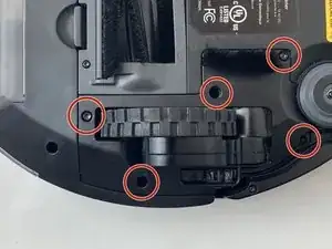
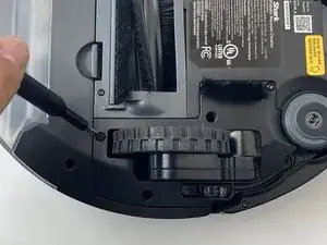
    • Using a Torx T15 screwdriver, remove the five screws from the drive wheel assembly.

    • Carefully lift the drive wheel assembly from the wheel well by gently pulling up on the wheel.

    • The assembly will still be connected to the motherboard via a cable, so be sure not to pull so hard that the cable rips.

    Be sure to include a markup shot showing the location of the five screws. Remove locate steps in all guides. Indicate how to remove the wheel assembly in the guide text. Use caution bullets for caution notes.

    Alex Watkins -

  6. UuVlCTqOrqpaKcfn
    UuVlCTqOrqpaKcfn
    D1lTIlGDV2kEgDrn
    HFWNJwPaj4FsDoO4
    • Flip the wheel assembly over and disconnect the cable connector on its underside.

    • Remove the drive wheel assembly.

    • Repeat this process for the other side if necessary.

    Add markup. Remove all reassembly guide text. Indicate how to disconnect the cable, not just to do it.

    Alex Watkins -

Abschluss

To reassemble your device, follow these instructions in reverse order.

Andrew Lowy

Mitglied seit: 25/01/20

572 Reputation

3 Kommentare

Where I can buy the Shark ION Robot R75 Drive Wheel Assembly Replacement?

Thanks for your help!

xoxolo -

Do you know what the drive wheel motor cable is (see Step 6)? It's a 6 pin to 5 pin and the grooves are on the thin side and pitch of ~1.4mm. Possible a JST ZH?

Seth T -

I appreciate the step-by-step instructions with pictures... this was very helpful. However, my rv750 doesn't have the screws by the wheel assembly.

I've removed the screws, but it appears that I will need to separate the bottom from the top to access the wheel assemblies. Do you have a step=by step for the rv750 that has the wheel assembly enclosed?

RandiB -