Einleitung

This guide shows you how to conduct a top cover removal of the Shark ION Robot R75 as a prerequisite for replacing more internal components such as the sensors, side brush motors, or motherboard.

  1. yd1jGlpLTDRc1hHf
    yd1jGlpLTDRc1hHf
    XNNtWHGMoY5GxiE5
    FEsGvqsPYxCsancT
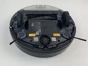
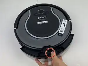
    • Make sure the robot is shut off by pressing the power button on top.

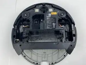
    • Flip the R75 over so that the underside is facing up.

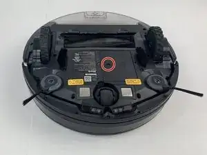
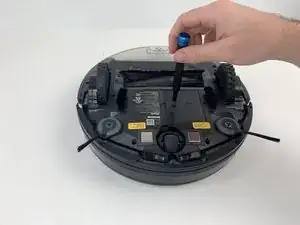
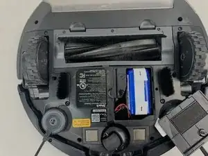
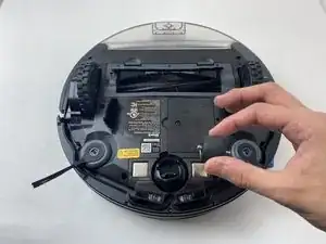
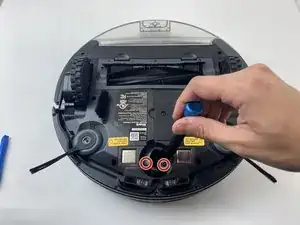
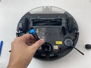
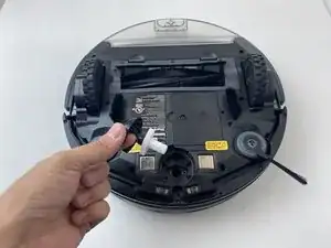
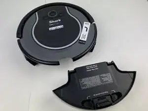
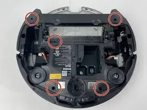
    • Using a Phillips #1 screwdriver, remove the 4mm screw in the battery cover.

    • Remove the battery cover.

    Here, you have misused the reminder bullet. The note bullet would be better in this case; I would also say how to turn it off, rather than just to do it. Avoid locate steps, and instead, move straight to the information about what to do. Use markup on the images to indicate where the component is. Be careful about using “remove” without other information about how to remove it, especially if there are multiple ways to remove something.

    Alex Watkins -
  2. eNek1rNlHGuxOQoA
    eNek1rNlHGuxOQoA
    guxEldPlLS5pacye
    GLpTIqMocSKtTEpG
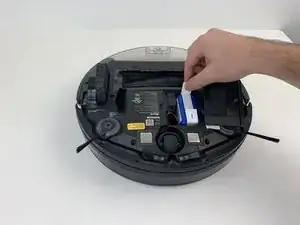
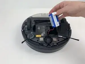
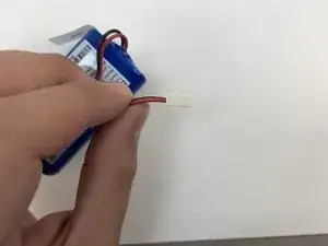
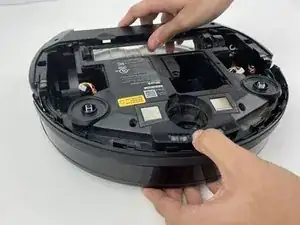
    • Be careful when removing the battery, as it will still be connected to a wire.

    • Slowly pull the white tabs outward to remove the battery.

    Make sure to review how to appropriately use special bullets. Make sure to check throughout to remove “locate” steps, and instead, just go straight to the action.

    Alex Watkins -
  3. CqrfN2ORRlhjOLfR
    CqrfN2ORRlhjOLfR
    TDLOlROYnNnNHnAK
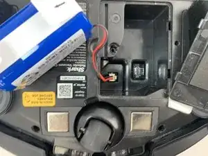
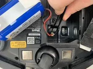
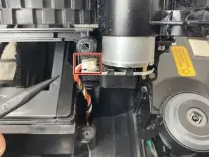
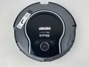
    • Be careful when removing the connector, as the part can break if too much force is used.

    • Push down on the tab of the battery connector using a set of tweezers and pull the connector away from the robot to free the wire.

    • Remove the battery from the device.

    Here, you’re using tweezers, but you don’t indicate that in the guide steps. Instead of including the information in the special bullet, I would just integrate the tool into the actual procedure. Do you have pictures of you pushing the tab? Can they yank the wire, or do they need to pull gently? I would add a flipbook style action shot to make the procedure clearer in the pictures.

    Alex Watkins -

  4. gXxtN1rTtH2bbtVW
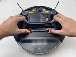
    • Push on the two tabs on the edge of the main brush cover and pull up to remove the cover.

    I would add markup and action shots here. Which cover? Make sure to specifically identify device components.

    Alex Watkins -

  5. cbAto6JJ5fOSuKW2
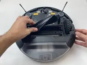
    • Pull the main brush slightly to the right to remove it from the compartment.

    When will you know that you’ve pulled far enough to the right? When you say remove, do you need to lift the brush up? Do you have more action shots demonstrating this procedure?

    Alex Watkins -

  6. CkxFh6Kf3J2hxc1H
    CkxFh6Kf3J2hxc1H
    EGfQVKqEZZ2dLGvT
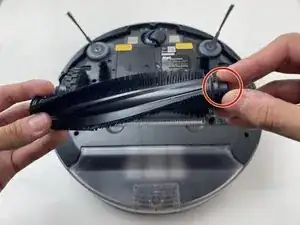
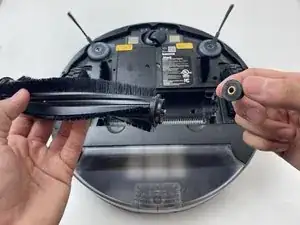
    • Remove the rubber end cap indicated by the red circle.

    • This step is not needed for a replacement. However, it is important for maintenance. Hair will build up in this area over time, and will cause error messages to pop up, as well as stopping the R75 from cleaning and moving.

    • Inspect this component at least every six months. This time may be less if you have animals.

    Be sure to check special bullets. Indicate how to remove the end cap.

    Alex Watkins -

  7. bWkmHLsO3DU6AdlU
    bWkmHLsO3DU6AdlU
    d3KbtBcmv1gCQ6VJ
    hD6dR2avOjJ6OmKm
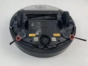
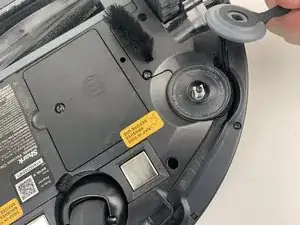
    • Grab the side brushes by the plastic tab at the base of the bristles, and gently lift up.

    • It's recommended to clean the area with a dry microfiber cloth during replacement, as debris can collect beneath the brush during use.

    The first step doesn’t seem necessary here. You can just include markup on the full shot to show the component you’re asking them to work on. Also, you don’t need to include cleaning/maintenance directions here, although you can include them in the introductions and/or the troubleshooting page.

    Alex Watkins -

  8. VtUDoejRD3vsoG6p
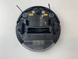
    • Flip the R75 to its underside.

    • Make sure the R75 is shut off.

    • For extra security, disconnect the battery by following the prerequisite guide.

    Here, the device was already oriented this way, so the directions on the side sensor with using this prerequisite make the procedure confusing. Make sure to read through all guides to make sure you don’t have these kinds of continuity errors. Also, include the battery replacement as a prerequisite for all guides, and use the system to include the prerequisites, rather than putting this information in the note.

    Alex Watkins -

  9. a22HkVXVdlQa5df1
    a22HkVXVdlQa5df1
    QqSNPmhse16yECIP
    kNHbFBibAC6q2QTO
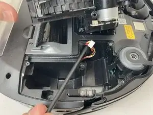
    • Using a Torx T15 screwdriver, remove the five screws from the drive wheel assembly.

    • Carefully lift the drive wheel assembly from the wheel well by gently pulling up on the wheel.

    • The assembly will still be connected to the motherboard via a cable, so be sure not to pull so hard that the cable rips.

    Be sure to include a markup shot showing the location of the five screws. Remove locate steps in all guides. Indicate how to remove the wheel assembly in the guide text. Use caution bullets for caution notes.

    Alex Watkins -

  10. UuVlCTqOrqpaKcfn
    UuVlCTqOrqpaKcfn
    D1lTIlGDV2kEgDrn
    HFWNJwPaj4FsDoO4
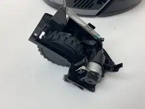
    • Flip the wheel assembly over and disconnect the cable connector on its underside.

    • Remove the drive wheel assembly.

    • Repeat this process for the other side if necessary.

    Add markup. Remove all reassembly guide text. Indicate how to disconnect the cable, not just to do it.

    Alex Watkins -

  11. DCFL2HGv51IPsO4h
    • Orient the device with the bottom facing up.

    This photo is not helpful. Is removing the whole assembly correct procedure, or could it break the device?

    Alex Watkins -

  12. 556RyN3NGPoFxTGl
    556RyN3NGPoFxTGl
    KC5IHBg3hMCSRkgZ
    hNXbxY2Es3iMfhMB
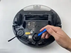
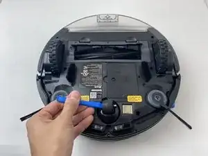
    • Using a plastic opening tool, pry first one side of the wheel, then the other out of the caster.

    • Remove the wheel.

    Note that you’re using a plastic opening tool, not a screwdriver. Be sure to appropriately identify tools. Proofread all guide text for clarity and end punctuation. For all remaining “remove” steps, if something can be done in multiple ways, then you need to indicate how. Remove is good for screws because there’s only one way to do that. For everything else, use more detail or a stronger verb.

    Alex Watkins -

  13. mwHttSYNROCIP4Vv
    mwHttSYNROCIP4Vv
    5MLiBvEBA2ew3rDM
    AKwqY6ZO4II5UAHi
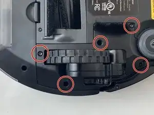
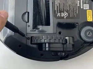
    • Using a Torx TR9 screwdriver, remove both screws from the caster assembly beneath the wheel.

    • Pull the caster assembly up from its slot in the device.

    Hi I have the same model but the screws are not on the outside and there is what appears to be like a ring like part that held the caster assembly in the slot I cant pop the assembly back in and nor does that white part come out can you please help me with that

    Hanisha Rush -

  14. RdROwgMdBt6Kj3Uj
    RdROwgMdBt6Kj3Uj
    ZicRypQ2DDp1Tcvy
    HIQFEFHHLOpsKCUR
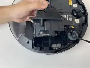
    • Push down on the black tab and remove the dust bin

    In the first image, the device looks significantly different for Step 13 to Step 14, then the device is flipped in the second and third images. Be careful about these kinds of continuity errors.

    Alex Watkins -

  15. 2vxgWrXiAJToGEB6
    2vxgWrXiAJToGEB6
    rYKbYqMAjEnZwIF3
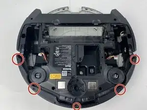
    • Using a Torx TR15 screwdriver, remove the five screws from the bottom cover.

    Use markup on images to show where components are. Past Step 15, here, I’m no longer marking this issue. Additionally, proofread all steps for end punctuation.

    Alex Watkins -

  16. EdvXB6NALqhd1UoV
    EdvXB6NALqhd1UoV
    SZYUMTlCVr6f2kDc
    PDueCUojs5kkrPg6
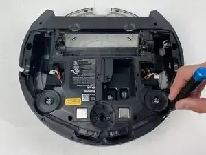
    • Make sure the robot is facing rearward

    • Using a Torx TR15 screwdriver, remove the five screws along the front edge of the device.

    • Pull the bottom part of the bump guard away from the body of the device.

    What does it mean to face the device rearward?

    Alex Watkins -

    Do you have pictures of you removing the bump guard?

    Alex Watkins -

  17. egRVoKgBseqQmx3I
    egRVoKgBseqQmx3I
    LDmUDsNcVY2ZfB2R
    NhAKRMuAwgMlRWX1
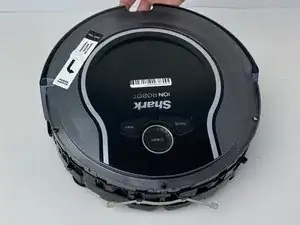
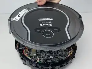
    • Lift the top cover up from the rear of the robot to separate the top cover from the rest of the robot.

    • Be careful when separating the top from the rest of the robot, as the plastic clips can break if excessive force is applied.

    • From here, easy access to all sensors, the main brush motor, and the fan are all granted.

    What is the difference between the two black bullets? Also, the information bullet is not necessary here.

    Alex Watkins -

Kyle Wilbourn

Mitglied seit: 25/01/20

492 Reputation

0 Kommentare