Einleitung
The Smart UF75 projector uses a Digital Micromirror Device (DMD) with 1024*768 small mirrors that move to switch each pixel on or off.
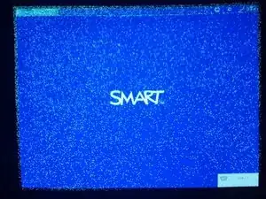
A faulty DMD displays black or white specks all over the screen where individual mirrors have stopped moving.
Werkzeuge
Ersatzteile
-
-
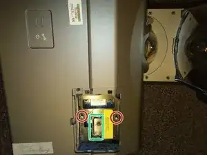
Use a flat screwdriver or coin to remove the flap covering the bulb module
-
Loosen these 2 Philips #2 screws. These screws should stay captive within the bulb module.
-
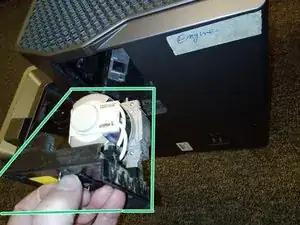
Lift this handle and pull out the bulb module.
-
-
-
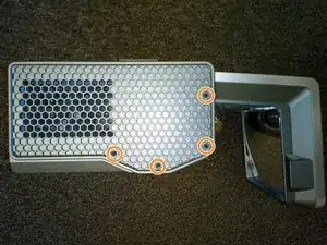
Remove these 3 black 5mm Philips #2 screws from the right side panel.
-
Remove these 4 black 5mm Philips #2 screws from the left side panel.
-
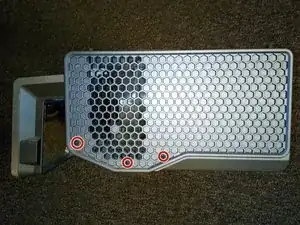
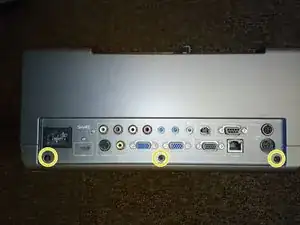
Remove these 3 black 5mm Philips #2 screws from the rear panel.
-
-
-
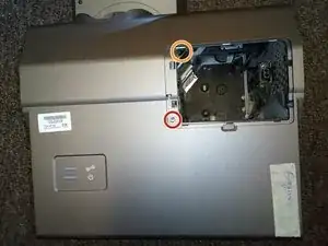
Remove this 7mm Philips #2 screw under the bulb cover.
-
Remove the 7mm Philips #2 screw deep in this hole. A magnetic screwdriver essential for removing and replacing this inaccessible screw.
-
The lid can now be removed by gently prising it off starting at the hole for the bulb.
-
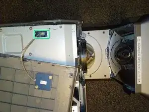
Unplug this cable then put the projector lid to one side.
-
-
-
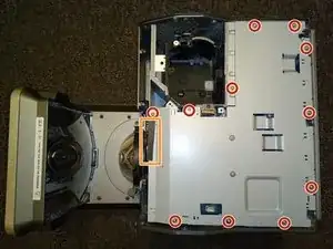
Remove these 11 silver 5mm Philips #2 screws from the metal cover.
-
Unpeel this black card that is stuck to the metal cover.
-
Lift off the metal cover to reveal the main circuit board
-
-
-
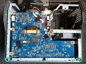
Remove these 2 silver 8mm Philips #1 screws and their white plastic washers then unplug the ribbon cable. This plug will drop through the hole in the board when you lift off the board.
-
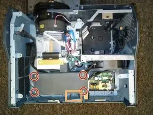
Remove these 6 silver 8mm Philips #2 screws from the main circuit board.
-
Remove these 2 silver 6mm Philips #2 screws that attach the board of plugs at the back of the projector.
-
-
-
Projectors built in 2010 have a small extra circuit board here. You can skip this step if you have a newer projector without this extra circuit board.
-
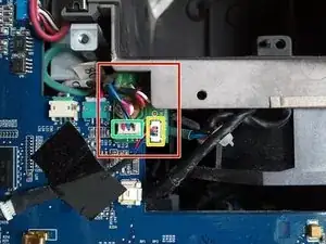
Unplug this wire from the small circuit board. Peel back the two pieces of tape holding down the wire, leaving one end of each piece of tape attached to the board for the later re-assembly
-
Remove the other plug from this small circuit board. The small circuit board is now free to come away with the main circuit board.
-
-
-
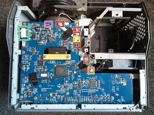
Unplug these 5 plugs. These plugs are stiff but there are no clips or catches to release. I used a combination of pliers and miniature side cutters to grip the two edges of each plug and work it loose.
-
Remove this plug by pressing down the back of the plug to release the catch
-
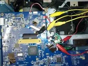
Gently remove this thin ribbon cable by pulling back the plastic plug then pulling out the cable. Untape the ribbon cable from the board.
-
Later models have an extra wire here that needs to be unplugged.
-
Remove this larger plug by squeezing the two ends to release the clips. On later models, this plug is underneath the board, so you will need to release it while you are removing the circuit board
-
-
-
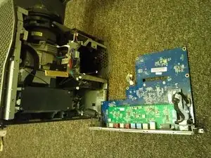
Remove the main circuit board by lifting the board from the back end where the external plugs are attached.
-
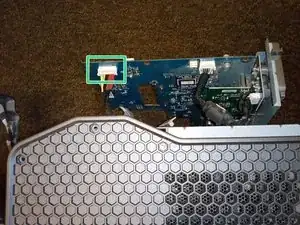
Unplug this mains plug.
-
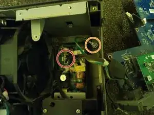
Disconnect the earth lead by unscrewing this silver 5mm Philips #2 screw with its captive serrated washer.
-
-
-
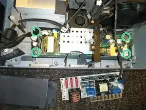
Remove these 4 silver 6mm Philips #2 screws to release the top power supply.
-
Peel off this cardboard that is glued to the power supply cover.
-
Unplug the large plugs at each end of the power supply and move the power supply out of the way. You can leave the smaller fan wire connected.
-
Remove these 4 silver 8mm Philips #2 screws from the lower power supply then move the power unit to the side, along with the card it is resting on.
-
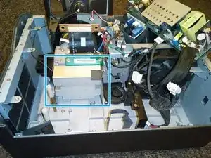
You now have clear access to the DMD heatsink.
-
-
-
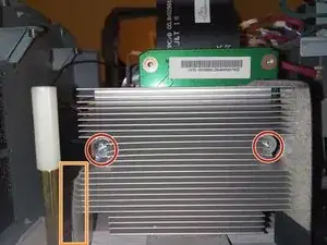
Remove these 2 Philips #2 screws holding the DMD heatsink. Two washers will drop down behind the heatsink when you remove these bolts. You will be able to retrieve these when you have removed the heatsink.
-
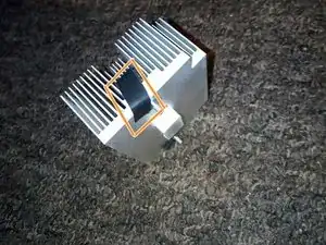
Peel back this sticky card to free the heatsink.
-
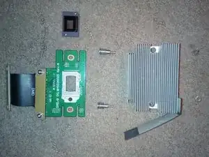
Pull back the heatsink then remove the DMD module
-
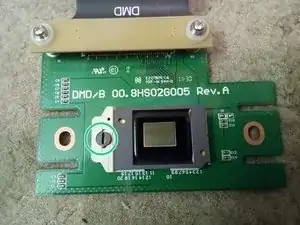
To remove the DMD chip, turn this screw half a turn anticlockwise.
-
-
-
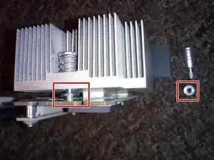
Re-fitting the spacer washer that fits between the heatsink and the DMD board is tricky.
-
Use a thin strip of electrical tape to hold the washer and bolt in place while you re-assemble. The tape can be removed before tightening the bolts.
-
To reassemble your device, follow these instructions in reverse order.
2 Kommentare
How much interoperability does the UF75 have with UF55/65?
Are the DMD chip, DMD module, colour wheel, or lamp compatible?
The documents I have found suggest that the DMD chips are not compatible. Here is a list of projectors that are compatible with the UF75 DMD chip: https://www.replaceyourlamp.co.uk/projec... and a different list of projectors compatible with the UF55 DMD chip: https://www.replaceyourlamp.co.uk/projec...
The lamps are different: the UF75 lamp is 230 watt but the UF65 lamp is 200 watt and the housings look slightly different.
I don’t know about the colour wheel compatibility.
David42 -
