Einleitung
Werkzeuge
Ersatzteile
-
-
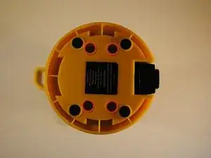
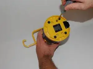
Flip lantern upside down and unscrew the 4 phillips head screws on the base and remove the base plate.
-
-
-
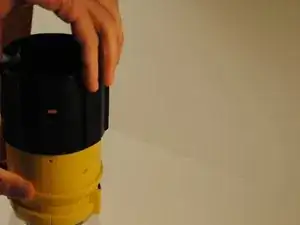
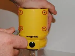
Slide the black rubber sleeve off of the outside of the body of the lantern away from the LED globe.
-
-
-
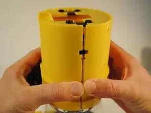
To disassemble the main body, grip the lantern so that the front half of the body with the power button on it is in your right hand and the back half with the hand crank is in your left.
-
Pinch the front half of the body on both sides with your thumb and index finger just below the first extruding rim of the front plate while simultaneously pulling the back half away. This may take some effort to do.
-
-
-
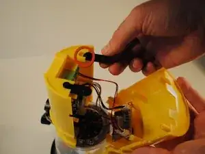
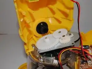
Locate the crank dynamo component. It is mounted on the back plate directly above the battery.
-
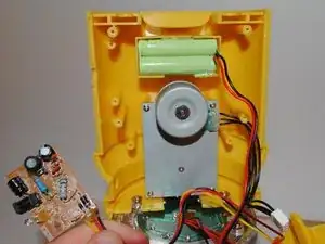
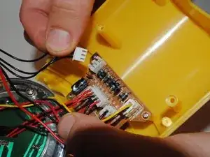
Trace the wires from the dynamo component to the main power board. Pull out the white clip from the socket on the main board. This will sever the electrical connection between the crank dynamo and the rest of the lantern.
-
-
-
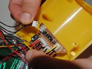
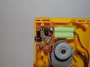
Locate the DC-in board. It is mounted onto the back plate slightly covering the bottom right corner of the crank dynamo.
-
Remove the two screws mounting the DC-in board.
-
Move the DC-in chip out of the way in order to access the crank dynamo.
-
-
-
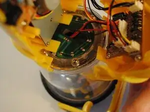
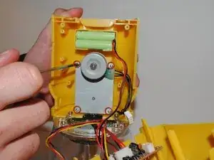
Unscrew the four screws mounting the crank dynamo component to the back plate.
-
Remove the crank dynamo from the lantern.
-
-
-
Place new crank dynamo where the old one was previously housed on the back plate. Make sure to align screw holes on the dynamo to those on plate.
-
Replace the four screws holding the dynamo in place.
-
Attach the wires from the new crank dynamo to the correct area of the main board where the old wires were removed.
-
To reassemble your device, follow these instructions in reverse order.
