Einleitung

There are two boards for the device, a green top level and a blue lower level. This guide will show the steps to replace the top motherboard.

  1. t3ilfDa1PNBQUnUG
    t3ilfDa1PNBQUnUG
    OaGRZiLqQFBGPdoF
    WViytRuORo34N2DC
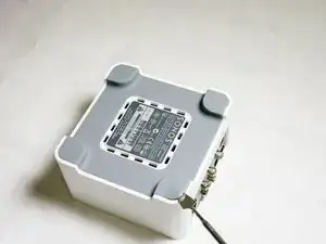
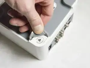
    • Start by using a spudger or plastic opening tool to remove the bottom cover.

    • When working with electronics, it's important to choose a tool that's ESD-safe to avoid accidental damage to the device. The regular black nylon spudger or a plastic opening tool should be used whenever possible.

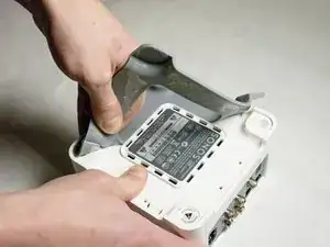
    • Once enough of the glue is removed, peel the cover off by hand,

    Careful as the rubber bottom rips extremely easily. Be very patient.

    marcos_peixoto1 -

  2. 4pLla12ZHRecHYWQ
    4pLla12ZHRecHYWQ
    D1Kg3jN4CUKMpRVD
    5HF54JLPJvFe1XEq
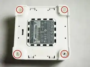
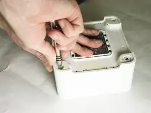
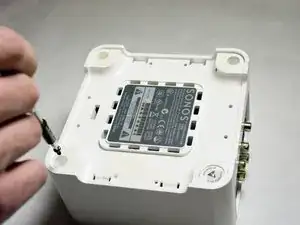
    • Remove the four 7.5mm length Philips head screws under the rubber cover.

  3. C1WM6TTTMXjKIe1C
    C1WM6TTTMXjKIe1C
    HVY622r6r3TmS5Rg
    yCxZiQgjbvFKtfQb
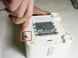
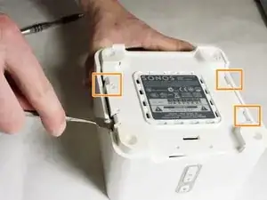
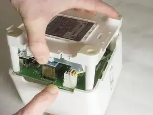
    • Use a nylon spudger to unsnap the bottom from the sides.

    • Pry until the remaining three points are unsnapped.

    • Once unsnapped, lift the cover.

  4. qWwnSunJaGytUXrB
    qWwnSunJaGytUXrB
    1SiMcPQItDhAQT4C
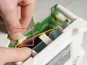
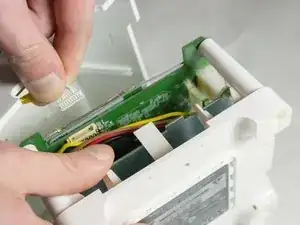
    • Remove the connection for the front buttons to fully remove the cover.

  5. AnwVh5pBJqVHD5dJ
    AnwVh5pBJqVHD5dJ
    YoYMHqvXvLsSMh2Z
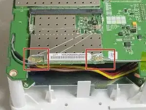
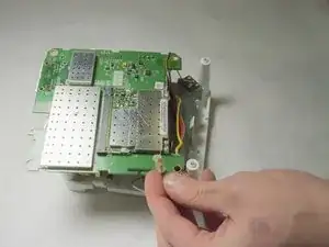
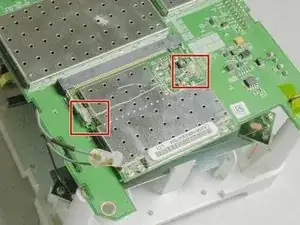
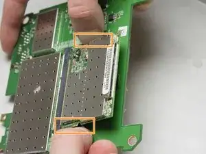
    • Use a plastic opening tool or spudger to remove the adhesive covering the the WIFI connectors.

    • Gently pull the wires at the connection point to disconnect them from the motherboard.

  6. fAqRmmsGB2EPo1yN
    fAqRmmsGB2EPo1yN
    WAMnDngSTNydhoC5
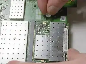
    • Remove the two pieces of glue holding the WIFI card in place.

  7. PkQvAEJxofVQaLTi
    PkQvAEJxofVQaLTi
    CRjYYjhjteJaJE4B
    3Mq1AvOqhPhQnNDa
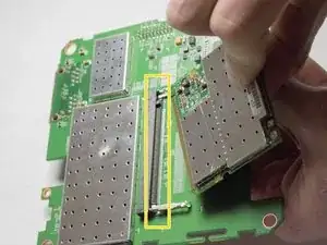
    • Scrape the glued pad underneath the WIFI card to seperate the card from the board.

    • Push apart the two clips holding the WIFI card in the connection.

    • Pull the WIFI card out of the connection.

    • When putting the new WIFI card in, put the card in the connector first, then push downward until it clicks.

  8. FJdqxUNQglrETsOJ
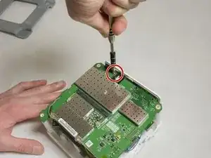
    • Remove the 7mm length Phillips screw holding the board in place.

  9. uPeBHYUUIFPKEG6g
    uPeBHYUUIFPKEG6g
    TtaNQeTYXMIhvsU5
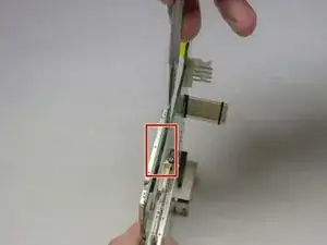
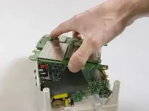
    • Flip the board over to access the Molex Cable.

  10. NiASugHTMpyEgKtK
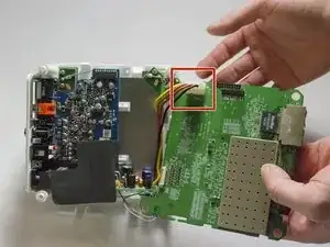
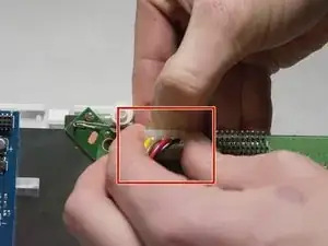
    • Disconnect the Molex Cable from the top motherboard.

Abschluss

To reassemble your device, follow these instructions in reverse order.
Clark Snyder

Mitglied seit: 21/01/16

483 Reputation

0 Kommentare