Einleitung
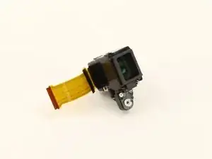
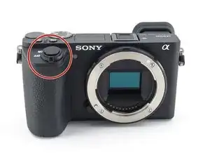
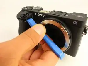
The viewfinder glass helps you frame the scene before taking the photo. A broken viewfinder glass will affect your ability to compose good pictures. This guide will walk you through the replacement of a broken viewfinder glass. Ensure that the problem with your viewfinder is not software related, and verify that the focus feature is working properly before considering replacement. The tools required for this replacement are a JIS 0 screwdriver, JIS 00 screwdriver, JIS 000 screwdriver, opening tools, spudger, and tweezers.
Werkzeuge
-
-
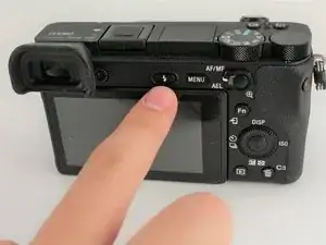
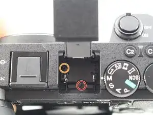
Press the flash popup button on the back of the camera.
-
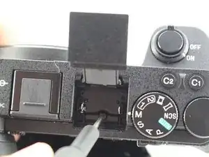
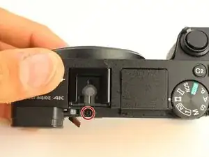
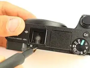
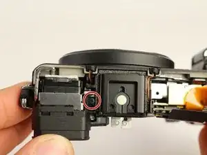
Remove one 5mm JIS 00 screw from inside the flash compartment.
-
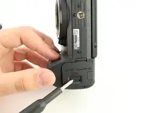
Remove one 4mm JIS 00 screw.
-
-
-
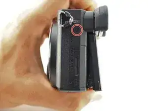
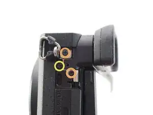
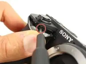
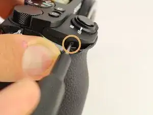
Remove the 2.5mm JIS 00 screw from the side of the camera near the viewfinder.
-
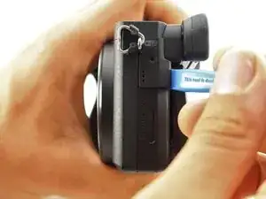
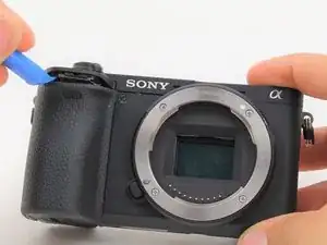
Use the opening tool to pry off the small cover.
-
Remove two 2.5mm JIS 00 screws from underneath the cover.
-
Remove a 5mm JIS 00 screw from underneath the cover.
-
-
-
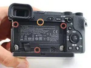
Remove three 2.5mm JIS 0 screws from the back face of the camera.
-
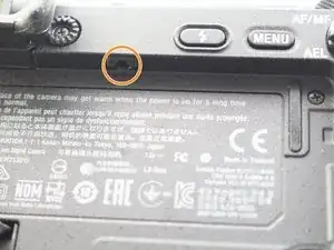
Remove one 4mm JIS 00 screw from the underside of the lip that overhangs the back of the camera.
-
-
-
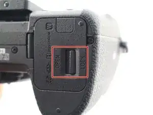
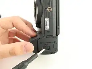
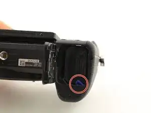
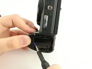
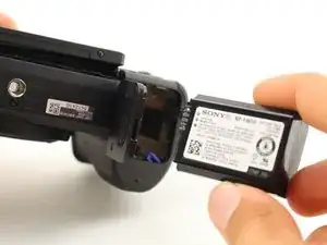
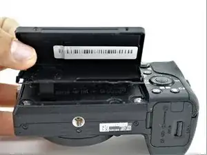
Flip the battery lock switch to open and open the battery compartment.
-
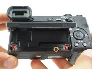
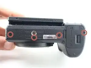
Remove three 2.5mm JIS 00 screws from the top of the battery compartment.
-
-
-
Use the plastic opening tool to begin prying off the back of the camera from the side.
-
Continue to loosen the back until you can open it from the bottom.
-
-
-
Open the back of the camera.
-
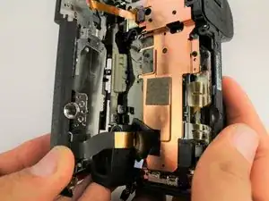
Use tweezers to remove two ribbon connectors from underneath the back. One connects to the LCD display and the other connects to the right side behind the battery compartment.
-
-
-
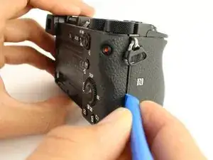
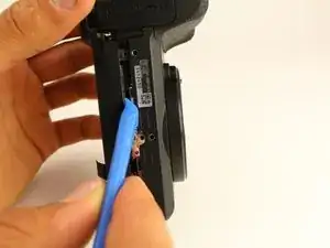
Use the plastic opening tool to peel down the rubber grip around the handle at least 1 cm.
-
Remove one 3mm JIS 000 screw from underneath the rubber grip on the right side.
-
Remove one 4mm JIS 000 screw from the left side.
-
-
-
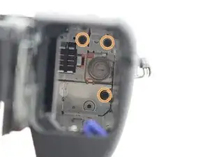
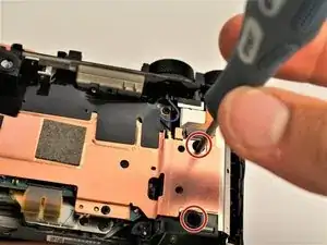
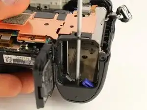
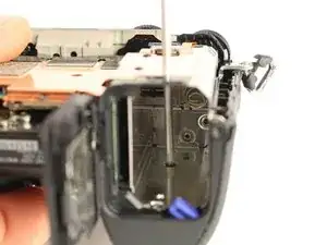
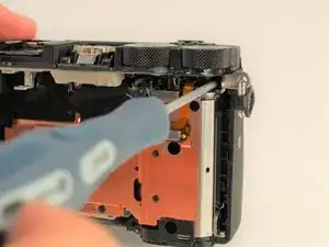
Insert a long, thin JIS 00 screwdriver through the two holes and into the battery compartment; remove the two 5mm JIS 00 screws inside it.
-
-
-
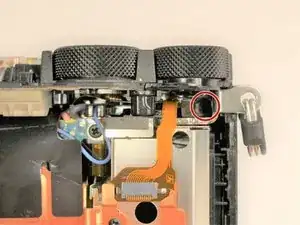
Use the long, thin, screwdriver to remove one 5mm JIS 00 screw inside the camera accessible below the dials from the back.
-
-
-
Use the plastic opening tool to gently lift up the shutter button assembly.
-
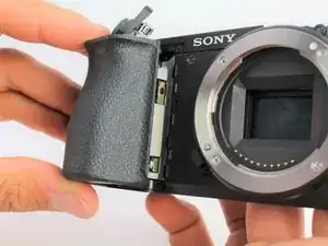
Grasp the front grip from the top and bottom and pull it off. It should come off easily with the shutter button out of the way.
-
-
-
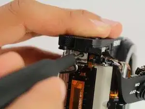
Remove one 2.5mm JIS 00 screw from where the shutter button assembly used to be.
-
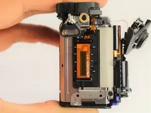
Remove one 3mm JIS 00 screw from the side of the camera.
-
-
-
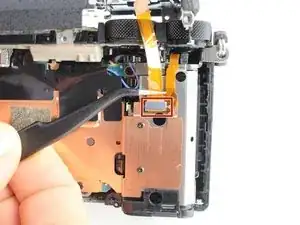
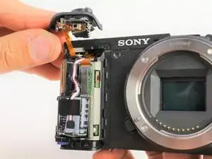
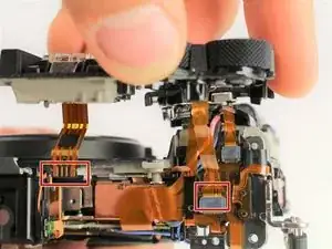
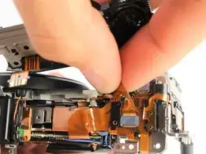
Carefully unplug the two ribbon connectors attaching the top assembly to the rest of the camera.
-
-
-
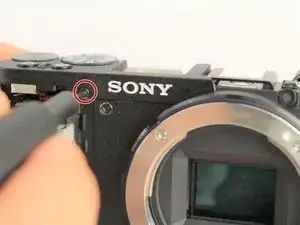
From the top of the camera remove one 4mm JIS 00 screw.
-
Remove one 5mm JIS 00 screw and the plastic bushing around it.
-
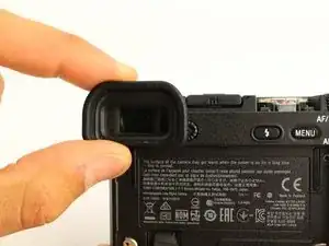
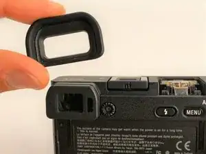
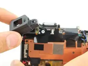
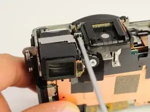
Remove the viewfinder's protective cover.
-
-
-
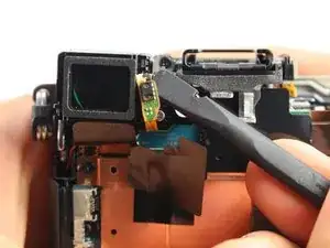
Use the spudger to pry the light sensor off the side of the viewfinder.
-
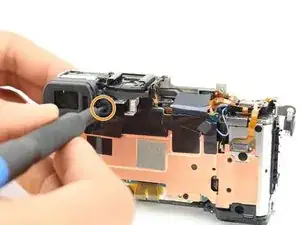
Remove one 2.5mm JIS 000 screw on the side of the viewfinder to release it.
-
-
-
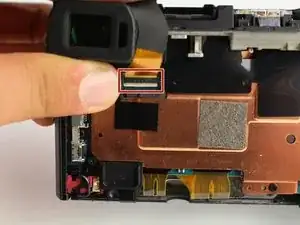
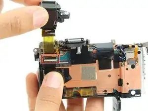
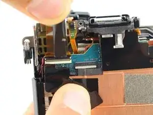
Lift the viewfinder out and flip up the tab to release the wire ribbon where it is connected to the motherboard.
-
To reassemble your device, follow these instructions in reverse order.
Ein Kommentar
This really helped me. I changed my VF unit with no problem. And btw, it is not necessary to unplug LCD cable. I havent done it, as i thought it would be really tricky to put it back in and it was just alright. Just tape the display to back panel while manipulating it so you dont twist the cables.
