Einleitung
This replacement is susceptible to breakage due to the amount of force that may be required for some of the removal process.
Werkzeuge
-
-
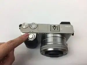
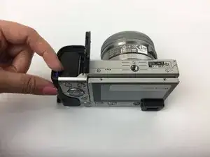
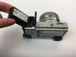
Flip the camera around to access the battery compartment.
-
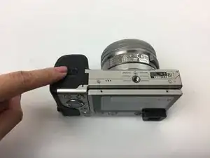
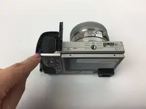
Slide the battery compartment lock to the left to unlock it.
-
-
-
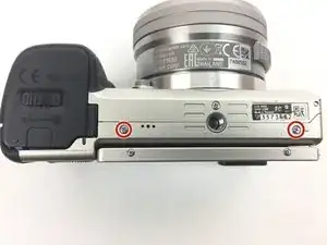
Turn the camera upside down and unscrew these two bottom 6 mm screws located on either side of the body by using the J00 head screw.
-
-
-
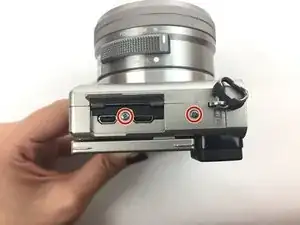
Turn the camera sideways.
-
Open the mini HDMI compartment and locate the two 6 mm screw underneath and another to the right of the compartment.
-
Unscrew using the J00 head screw.
-
-
-
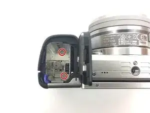
Locate the two 4 mm screws within the battery compartment and unscrew them using the J00 screw head.
-
-
-
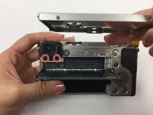
Bend the camera's screen forward to uncover two 3 mm screws below the eyepiece.
-
Locate them and unscrew them.
-
-
-
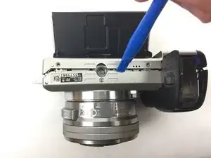
Use a plastic opening tool around the body of the camera to wedge the back cover off. Start from the bottom next to the battery compartment.
-
If necessary, lightly use your hand to pull the the back cover down to completely remove it.
-
-
-
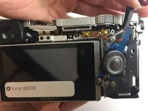
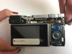
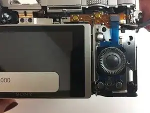
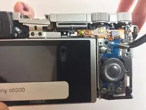
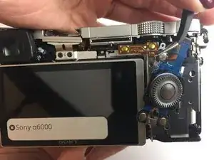
Once the back cover is removed, using tweezers, pull to remove the ribbon cable that is holding the settings wheel.
-
Now you can pull the settings wheel out of the camera.
-
To put the camera back together, follow these steps in reverse order.
2 Kommentare
I am trying to remove the back so I can remove the USB cover and hing as the cover is broke. If I fallow these instructions will I get to that pin?
Nate -
Quiet nice instructions… but you are missing a few important steps which are necessary to avoid damage:
1) You forget to mention the 3rd screw at the entry of the battery compartment.. in your picture of step 8 it is allready loose. It is not possible to remove the back panel without loosening of that screw.
2) It is much easier to remove the back panel, if you lift up the top panel, therefor you should loosen the two J00 screws under the internal flash.
3) You forget to mention that there needs to be a screw removed at the “dioptre correction wheel”, therefor the central small rubber patch needs to be removed with tweezers, then the underlying J00 can be unscrewed and the “dioptre correction wheel” removed.
4) Once the back panel has then carefully be loosened with a plastic opening tool you should be able to remove an additional screw of the eyepiece (right side), so that the eyepiece cover can be lift off, and then the backpanel is much easier to be removed.
Look for youtube “Dissasembly A6000”!
