Einleitung

This guide provided instruction on removing the motherboard and should only be followed if a compatible replacement is available or subsequent repair procedures require its removal.

  1. TJELFvgUORKCjE1a
    TJELFvgUORKCjE1a
    Q5fFP1KeGRJEvscy
    UVCGfZorLrAwBbXD
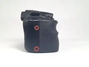
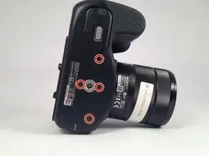
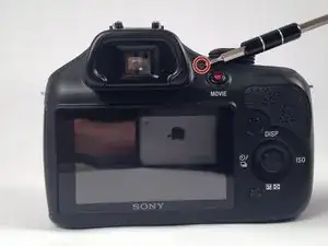
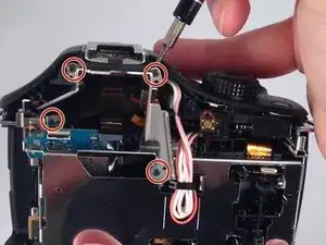
    • Remove the seven highlighted screws shown here.

    • Screws are teeny tiny, don't lose them!

  2. Oj1Y6FfI2IFUjThW
    Oj1Y6FfI2IFUjThW
    tJgLEm5l6sB6C1Sr
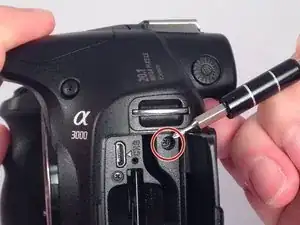
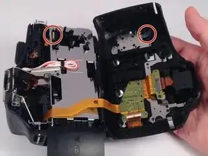
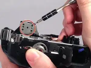
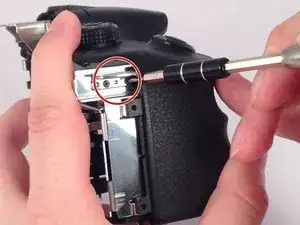
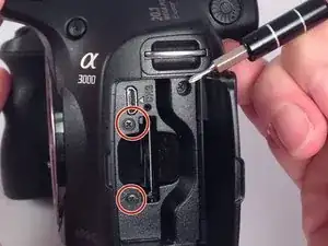
    • Remove this final screw from the memory card compartment.

    • Remove the chassis by pulling the back cover away from the camera.

    • Be careful not to damage any of the delicate ribbon cables when removing the chassis.

  3. aIABiCBKEleSmBf4
    aIABiCBKEleSmBf4
    kdXCiZTDUqqUFCTL
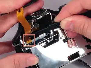
    • Gently but forcefully lift up on the parallel cable connecting the two halves of the camera.

  4. krk2xUccnWf5BSTH
    krk2xUccnWf5BSTH
    xA35JHCeHKbIkBL5
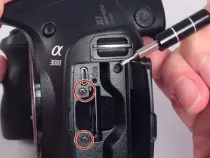
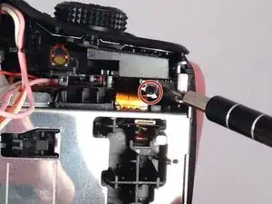
    • After removing the backing from the camera. Remove the two final screws in the memory compartment area.

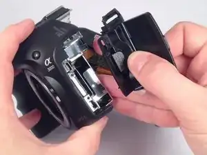
    • Detach the facing for the memory dock.

  5. dXS1eZydlCXDFj5e
    dXS1eZydlCXDFj5e
    yAQ3LiN31qffCK6X
    • Remove the eight screws securing the mount for the flash device.

  6. mVnSiPfVHcslKalN
    mVnSiPfVHcslKalN
    pdXPfSsBYuPNPKFo
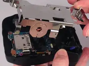
    • Remove the three remaining screws holding in the protective metal casing.

  7. VPumEdrKnxbKecIF
    • Remove the metal casing.

  8. on5mtuVEihHIYxOg
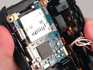
    • Remove three screws holding down the motherboard .

  9. NNsUB11kwq16wWBw
    NNsUB11kwq16wWBw
    vISr6YELpeFqppbk
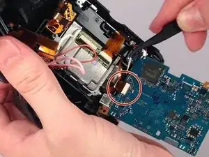
    • Detach the nine serial cables connecting it to the camera body.

  10. ERqBgvxXiITRTHXm
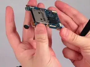
    • Finally remove the motherboard from the casing.

Abschluss

To reassemble your device, follow these instructions in reverse order.

Leonard Holloman

Mitglied seit: 31/08/15

626 Reputation

Ein Kommentar

Then loose the plug all the motherboard?
kongre172 -