Einleitung

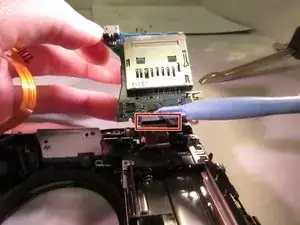
Replacing the motherboard may seem like a daunting task but can be done using prying tools.

  1. ZIvaQprEdf3fxXrD
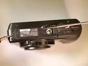
    • Orient the device so the bottom is facing up, and the lens is facing you ("bottom view").

    • For further reference, consult the service manual. Link to service manual.

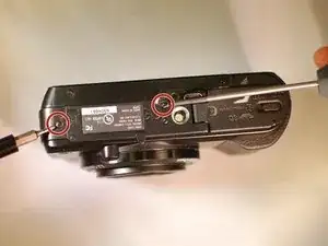
  2. 5hQOgICWlmYqBjHL
    • Remove these two black M1.4 X 3.5 Phillips head screws.

    • The third, unmarked screw does not need to be removed at this time.

  3. IuK6vBNJALNGimWy
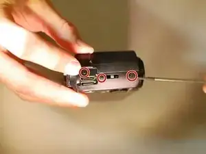
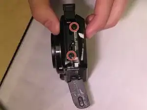
    • Orient the device so the LCD is facing you, and the hdmi cover is facing up ("left view).

    • Remove these three black M1.4 X 3.5 Phillips head screws.

    • You must lift the hdmi cover to expose one of the screws.

  4. TgsuIlLKGxDFj1oM
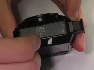
    • Orient the device with the Wifi/GPS logo facing up ("right view").

  5. ILUAbP5KpG2JRseS
    ILUAbP5KpG2JRseS
    A2LK2LCFUXW4ZYdS
    UbpZcewBpUZQW3Y5
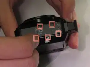
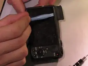
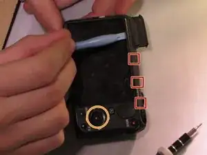
    • Use a prying motion and a plastic opening tool to pry the side panel up.

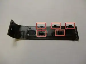
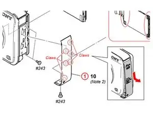
    • Areas under the squares are approximate locations of retaining claws, shown at right.

    • Be careful not to break any of the retaining clips as you pry up this panel.

    • An image from the Service Manual has been added, which shows this side cover should be slid down before being removed, not just pried up as shown in the first picture in this step.

    Pull the panel down there are 2 clips in the midtle be carefull not to brake them

    Kent Gunnertofht -

    Just prying doesn't do it. there are some clips which are really easy to break!

    I think it needs to be slided down!

    andreas -

    It is not clips but "hook" so to the mouvement should be at opposite direction on flash

    Olivier Lempereur -

    I inserted an opening pick under the lower part of the panel (where it was loosest; at the left of the photo) and then inserted a jimmy along one side (at the top of the photo). Then I pushed the panel down from the top (at the right in the photo) and it popped off.

    Chris Degnan -

    I Broke my two clips, will gluing them help put them back together?

    Ricardo -

  6. vru13QZXaAMhHgsX
    • After removing the panel, remove the two black M1.4 X 3.5 Phillips head screws.

  7. Tl3oMYYqHJ1p2Ide
    • Orient the device so that the LCD is facing you ("back view").

    take car around Menu button area - rear cover could broke.

    Olivier Lempereur -

  8. EQUNFmxDIAUjIs1E
    • Use the plastic opening tool with a prying motion, going between the case and the LCD, from the middle of the LCD to the right of the device, undoing the claws retaining the back.

    • When replacing the back cover of the device, ensure the flash module is UP.

    • The back cover should come off easily but you might hear light snapping or popping.

    • The rotary wheel and button are not secured. They will come loose when the back cover is removed. Set them aside for reassembly

  9. fHYBoOEsYaJd3W1o
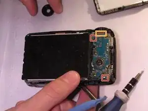
    • Unhook the small printed circuit board by gently pressing the board towards the top of the device and lifting up.

    • Note a ribbon cable should be attached at the top. This does not need to be disconnected yet.

  10. PlMieIHYQblGIwjD
    • Using a plastic opening tool remove the black LCD retainer clip to the right of LCD.

    • Note the orientation of the black LCD retaining clip and how it comes out of the camera.

    • If in doubt, consult the service manual. (Pages 25-27) Click to continue to the service manual. This has a reference number of 3 in the linked diagram.

  11. YObPWSXFR4RUMFlw
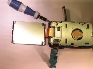
    • Use the plastic opening tool to gently lift the LCD from the device

    • The LCD should be attached to a ribbon cable

  12. lNRckAj1brE34H2V
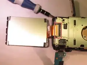
    • Using the plastic opening tool to lift the black retaining clip up to disengage the ribbon cable. Then gently pull the ribbon cable to remove.

    • Be careful to not damage the cable.

    when screen cable is plug, you can test before reassemble the device.

    Olivier Lempereur -

    Help this is an urgent need please !!! I am stuck at step 12 : lifting the black retaining clip up just pops it out like a pop corn (tried several times) and then nothing moves :-(

    larosedu92 -

    No need to unplug the LCD, to take the lens

    Il est inutile de débrancher l’écran LCD pour retirer l’objectif

    Thomas BERNARD -

  13. iEY2xEtMeYpx2dSt
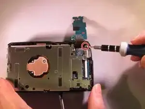
    • Remove the black M1.4 X 3.5 Phillips head screw in upper right corner of device.

    • If you have already removed the lens block, or aluminum back plate, you can skim over the next couple of steps until you are at a familiar place.

  14. wOYZqqDpWlONLQZF
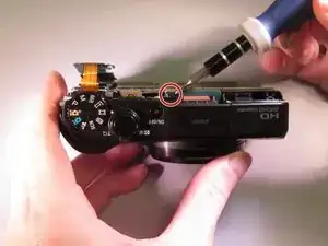
    • Reorient the camera so you are looking at the "top view".

    • Remove the black M1.4 X 3.5 Phillips head screw just below the ON/OFF button circled in red.

  15. IUbxstZmWyVfoM3F
    • Orient the device so you are looking at the "bottom view".

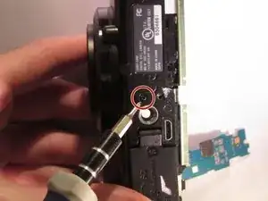
    • Remove the black M1.4 X 3.5 Phillips head screw located next to the tripod attachment.

  16. 5LMgkSQBLESvxmHV
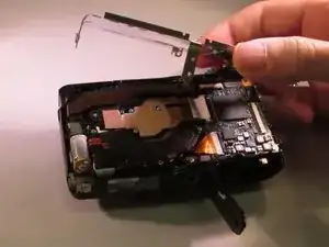
    • Lift the aluminium back plate.

  17. n4SNDXRaJnTGZfZd
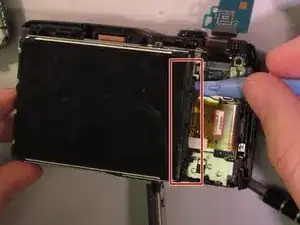
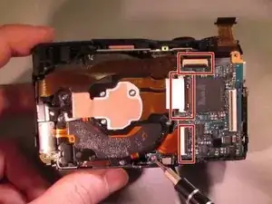
    • The connections (red squares) have small black retaining clips. Using a plastic opening tool, lift upward towards the cable to unlock.

    • After detaching retaining clips, gently lift to disconnect the ribbon cables.

    • Don't rip the cables.

    I ripped the cables can i get new ones

    Sameer sharma -

  18. k5NpDFqldwBkCgih
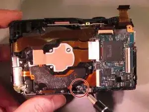
    • Remove the orange M1.4 X 3.5 Phillips head screw located near the bottom of the camera.

    • This is the only screw that is orange.

  19. T1qEC1SkpAldfWBs
    • Lift up the motherboard.

    • In this picture the lens block is removed, but it is not a necessity.

    • Disconnect the ribbon cable on the bottom by gently pulling.

Abschluss

To reassemble your device, follow these instructions in reverse order.
Bryson O'Neill

Mitglied seit: 08/04/15

528 Reputation

0 Kommentare