Einleitung
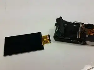
This guide will allow the user to remove the LCD screen from the camera to be replaced.
Werkzeuge
-
-
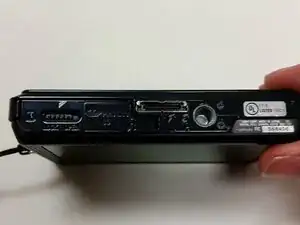
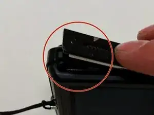
The battery compartment is located on the bottom of camera.
-
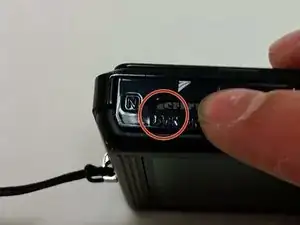
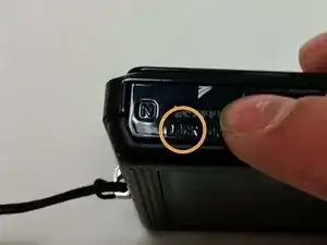
Move the slider from the 'lock' position to the 'open' position.
-
-
-
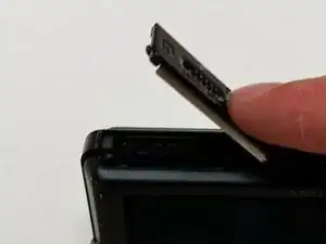
Pull battery from compartment.
-
Insert newly charged battery into compartment, as shown in diagram (located in compartment).
-
Shut compartment door.
-
Move the slider back to the 'lock' position.
-
-
-
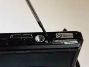
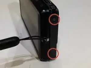
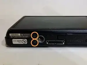
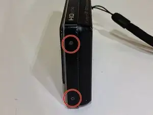
Use the Phillips #00 screwdriver to remove the 4mm length screws. There are 6 screws total.
-
-
-
The 4 mm length screws are located on each side and on the bottom of the camera.
-
2 screws on each side (4 total).
-
2 screws on bottom.
-
-
-
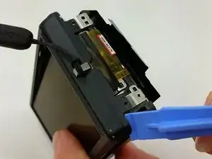
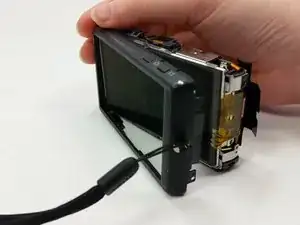
Gently pry around the front cover using the plastic opening tool.
-
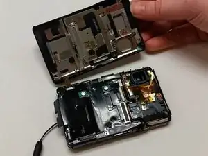
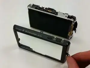
Carefully separate front cover from body of camera.
-
-
-
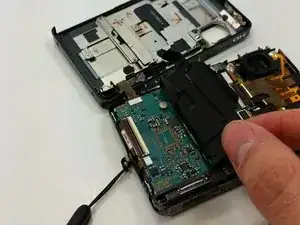
Peel the black sticker from the motherboard.
-
Locate the connection ribbon between the front cover and the body of the device.
-
-
-
Use the plastic opening tool to separate the back cover from the inner hardware.
-
Continue until back cover can be pulled away from inner hardware.
-
-
-
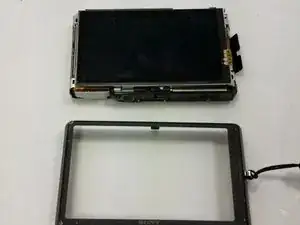
Remove the back cover so that the back cover is now completely separate from the body of the device.
-
-
-
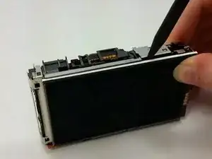
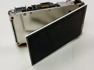
Pry the LCD screen using the spudger from the back of the camera.
-
Flip screen away from body of device.
-
-
-
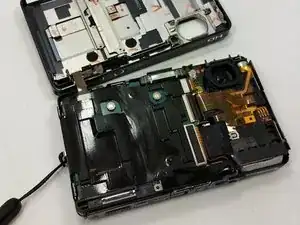
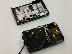
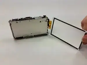
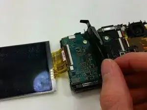
Lay the camera as shown, so that screen and camera body are next to each other, connected by the yellow ribbon.
-
Peel back the black sticker covering the motherboard.
-
-
-
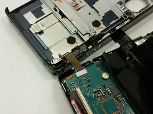
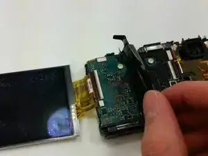
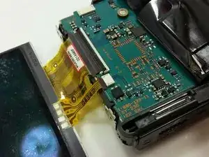
Locate the yellow ribbon's connection port.
-
Flip the black bar holding the ribbon in place toward the body of the camera.
-
-
-
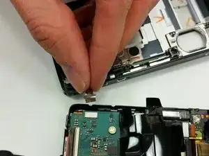
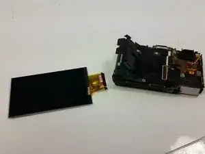
Pull the yellow ribbon out of the connection port.
-
The LCD screen is now separate from the body of the device.
-
To reassemble your device, follow these instructions in reverse order.
2 Kommentare
Very nice guide... Could you provide a dealer where it is possible to find spare parts for Sony cameras?
where can I find a new screen?
