Einleitung

Occasionally the LCD screen or the Back light on the camera will be cracked or simply stop working. This page outlines how to disassemble the camera in order to install replacement parts for any broken pieces.

  1. PLTicmKmcCon5OZE
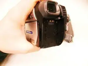
    • Images do not show the camera's battery.

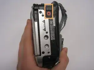
    • On the back of the camera beneath the viewfinder, locate the battery pack.

    • Press the small button.

    • Slide the switch forward.

  2. ULXdphhCbIUAFRJw
    • Remove the battery from the camera.

    • To reinsert the battery, slide the battery into the camera.

  3. dcSN2nErUW5J2CSr
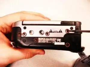
    • Using a #00 Phillips screwdriver, remove the six 4.5 mm screws from the camera's bottom.

  4. vlOZuFtQrAjlp1Sq
    vlOZuFtQrAjlp1Sq
    MBWKrZVpqORP3LVi
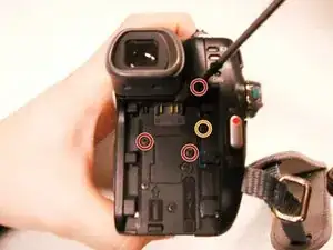
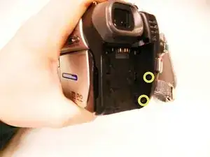
    • Remove the three 4.5 mm screws beneath the battery.

    • Remove the 2.9 mm screw from the right corner.

    • Remove the two 4.5 mm screws from the battery's right wall.

    • Images do not show the battery.

  5. lAPiOvsHTlqcbpOl
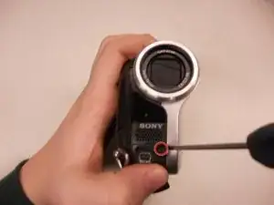
    • Remove the 4.5 mm screw under the output flap on the front of the camera below the lens.

  6. cQrLlb5hJQ3LQObO
    cQrLlb5hJQ3LQObO
    l4im6sOFktAPgPax
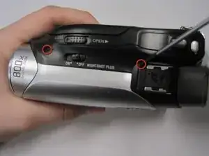
    • Remove the two 4.5 mm screws at the top of the camera.

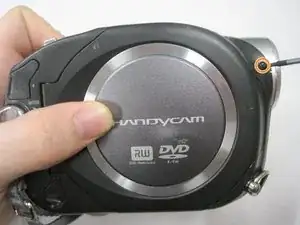
    • Remove the 4.5 mm screw from the disk side of the camera (next to the lens).

  7. wEXYBjwVHZAWASLj
    wEXYBjwVHZAWASLj
    VFXZUwppk5FwUylP
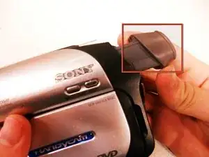
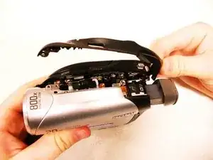
    • Extend the gray viewfinder, then gently remove the black plastic casing.

    • Caution: Plastic pieces are fragile.

  8. QcQfdQamrO2GbyXU
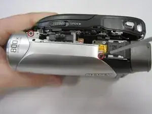
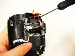
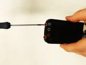
    • Remove the two 2.9 mm screws under the black plastic casing.

  9. KblSqgLgbnPlsqsR
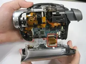
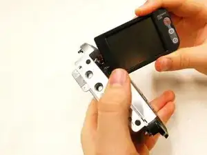
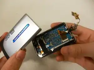
    • Gently pull apart the outer silver case and screen.

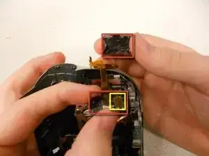
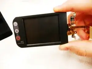
    • Remove the copper wire strip to detach the case from the camera.

  10. u4HKdHkpKgRkyuFU
    • Remove the copper strip from the housing that connects the outer casing to the entire of the camera.

    • Use caution when removing the wire, too much force may cause it to tear.

  11. M34DOWgjTvrUeBSC
    M34DOWgjTvrUeBSC
    GKccGoEf1PTxEnXF
    PCYHWxOWLoHDVxGN
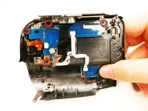
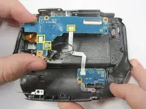
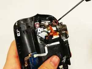
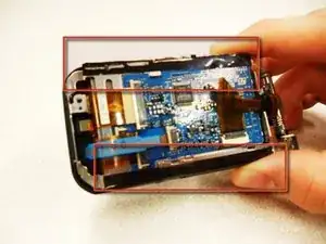
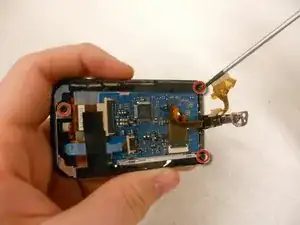
    • Remove (4) 2.9mm screws from the L-shaped circuit board. They are marked with red circles in the slide.

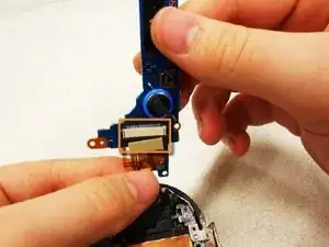
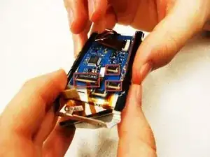
    • Remove the (3) wire strips connected to the camera so you can pull off the L-shaped circuit board.

    • Remove the single wire strip that is connected to the bottom of the circuit board.

  12. Oluu4n2EOLRNEwlm
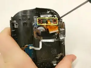
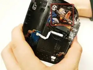
    • Remove the (2) 4.5mm screws.

    • Remove the small black holder from above the base of the LCD screen.

  13. eEEr3WYTKmqClvaP
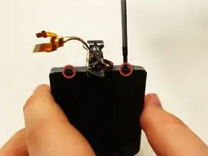
    • Remove (1) 2.9mm screw from the base of the LCD screen.

  14. XH6Wyta6XXBDMFwH
    • Remove the silver and black, front and back casings from the base of the screen.

    • Remove one copper strip from the inside of the bottom case.

  15. WDXYDIarbORnQJJN
    • Remove (2) 5.4mm screws that are securing the screen to the cover, from the base of the LCD.

  16. Dy3ZcjYGhbHlkQsG
    Dy3ZcjYGhbHlkQsG
    HikjPpH3VUhGvGU2
    yoZRQk64LWFiPSbt
    • Twist out the screen from the cover.

    • Be careful not to break the casing when trying to get the screen out, as it does require some maneuvering.

  17. SdUAHGBcLX5KaLef
    • Remove (2) 3.8mm screws from the end of the LCD.

  18. jAo6VbgZrBlilRwB
    • Remove (2) 3.8mm screws from the bottom of the LCD.

  19. 1WQiMjqk5kXlboWO
    1WQiMjqk5kXlboWO
    LC4XhViA1bH2XTbs
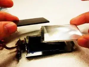
    • Pull off the silver cover on the screen, which will reveal the circuit board from behind the screen itself.

    • Pull off the black tape stuck to both sides of the circuit board.

  20. ACPQG6dOGSPi3rpt
    • Remove (3) 4.5mm screws from back-side of the LCD.

  21. mguls3J4WBgZGFJX
    mguls3J4WBgZGFJX
    5AfGZkSSrVwBIBhU
    MNBy45JbEyGETaJE
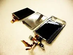
    • Remove the (3) copper strips to remove both the screen and the back light.

    • Replace what is broken.

Abschluss

To reassemble your device, follow these instructions in reverse order.
kaitlin

Mitglied seit: 11/01/11

342 Reputation

0 Kommentare